I recently purchased two 23cm WA5VJB PCB 3el yagi antennas without SMA connectors, that was a deliberate decision as I wasn’t sure how I would use or mount the PCB yagi. For a recent SOTA activation I quickly soldered a short length of RG174 to the PCB pads which served its purpose for two activations, Mt Taylor and Booroomba Rocks. My improvised RG174 solution was not meant to be permanent so it’s time to fix a SMA socket to the board.
WA5VJB 23cm 3el Yagi antenna, without a SMA socket

WA6VJB 23cm 3el PCB Yagi
Female SMA socket. The width of the socket base fits neatly on the PCB pad 🙂

Female SMA PCB mount
One edge of the SMA socket is soldered to the board’s ‘braid’ solder pad. The SMA center pin is sitting 3 mm above the board. I made up a short 8 mm length of 1.5 mm copper wire to extend the SMA center pin to the strip line folded dipole. I will leave the outer pins in place, their presence will help to protect the SMA center pin.

side view – SMA socket soldered in place
SMA socket soldered in place

antenna axis view
To help protect the strip line I sprayed the board with a light cover of PCB lacquer.
Finished and ready for portable use, VSWR reading is 1:1.
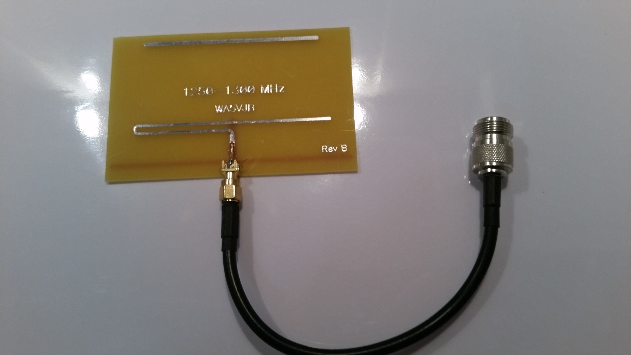
WA5VJB 23cm PCB Yagi connected to a LMR195 pigtail terminated with a female N Type socket. VSWR reading is 1:1.
Good luck with your 23cm SOTA activations. 😉
Photos: © Copyright 2017 Andrew VK1AD


