Yaesu FT-857D transceiver
Photos: © Copyright 2013-2017 Andrew VK1AD. All Rights Reserved
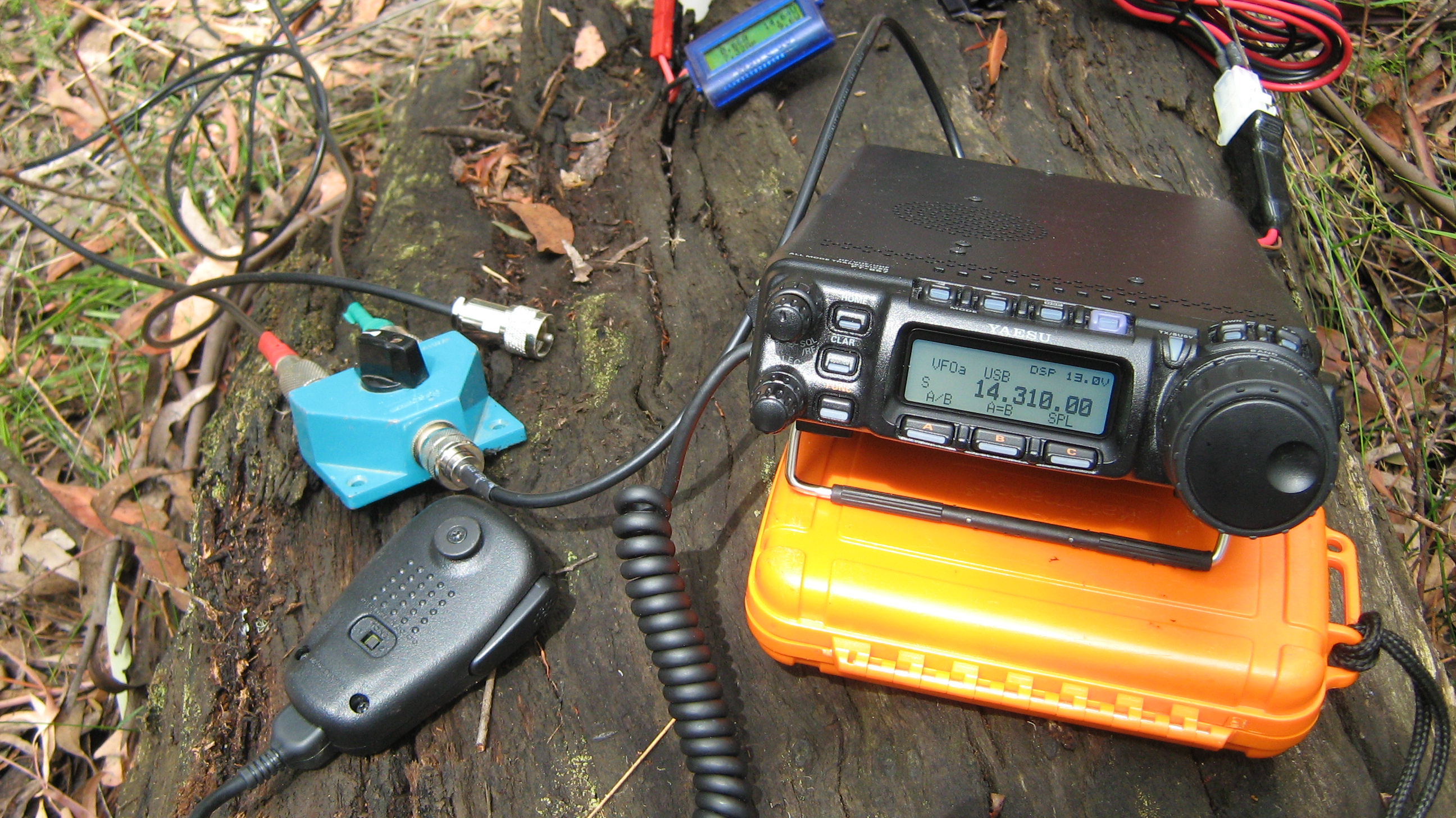
FT-857D deployed for a SOTA activation of Mt Little Joe VK3/VC-027 in Melbourne’s outer-east
Yaesu FT-857D Menu Settings – My preferred configuration for a typical SOTA activation
| No | Menu Item | Function | Available Values | Default |
| 001 | EXT MENU | Enables/Disables the extended Menu Mode. | ON/OFF | *** ON |
| 002 | 144 MHz ARS | Activates/deactivates the Automatic Repeater Shift feature when operating on the 144 MHz band. | ON/OFF | *** ON |
| 003 | 430MHz ARS | Activates/deactivates the Automatic Repeater Shift feature when operating on the 430 MHz band. | ON/OFF | *** ON |
| 004 | AM&FM DIAL | Enabling/disabling the DIAL knob on the AM and FM modes. | ENABLE/DISABLE | *** ENABLE |
| 005 | AM MIC GAIN | Adjusts the microphone gain level for the AM mode. | 0-100 | 50 # 30 |
| 006 | AM STEP | Selects the tuning steps for the MEM/VFO CH knob on the AM mode. | 2.5/5/9/10/12.5/25kHz | *** 2.5 |
| 007 | APO TIME | Selects the Auto Power Off time (time before power goes off). | OFF/1h-6h | OFF |
| 008 | ARTS BEEP | Selects the ARTS beep mode. | OFF/RANGE/ALL | RANGE |
| 009 | ARTS ID | Enables/disables the CW identifier during ARTS operation | ON/OFF | OFF |
| 010 | ARTS lDW | Stores your call sign into the CW identifier. | – | YAESU |
| 011 | BEACON TEXT 1 | Stores the message for the Beacon. | – | – |
| 012 | BEACON TIME | Selects the interval time (between message and message). | OFF/ 1 sec-255 sec | OFF |
| 013 | BEEP TONE | Selects the beep frequency | 440/880/1760Hz | 880Hz |
| 014 | BEEP VOL | Selects the beep volume level. | 0-100 | 50 ^ Adjust to suit |
| 015 | CAR LSB R | Sets the Rx Carrier Point for LSB | -300 ~+300Hz | *** +150 Hz |
| 016 | CAR LSB T | Sets the Tx Carrier Point for LSB | -300 ~+300Hz | 0 Hz |
| 017 | CAR USB R | Sets the Rx Carrier Point for USB | -300 ~+300Hz | *** -150 Hz |
| 018 | CAR USB T | Sets the Tx Carrier Point for USB | -300 ~+300Hz | 0 Hz |
| 019 | CAT RATE | Sets the transceiver’s circuitry for the CAT baud rate to be used. | 4800 bps/9600 bps/38400 bps | 4800bps |
| 020 | CAT/LIN/TUN | Selects the device which is connected to the CAT/ LINEAR jack on the rear panel. | CAT/LINEAR/TUNER | CAT |
| 021 | CLAR DIAL SEL | Defines the “control” knob to be used for setting of the clarifier offset frequency. | SEL, MAIN | SEL |
| 022 | CW AUTO MODE | Selects whether the KEY jack shall be “Enabled” or “Disabled'” while using the SSB/FM modes. | ON/OFF | OFF |
| 023 | CW BFO | Sets the CW carrier oscillator injection side on the CW mode. | USB/LSB/AUTO | USB |
| 024 | CW DELAY | Sets the receiver recovery time during pseudo VOX CW semi-break-in operation. | FULL/ 300 ~ 3000 ms | 250msec |
| 025 | CW KEY REV | Sets the keyer paddle’s wiring configuration. | NORMAL/REVERSE | NORMAL |
| 026 | CW PADDLE | Enables/disables CW keying by the microphone’s [UP/DWN] keys. | ELEKEY/MIC KEY | ELEKEY |
| 027 | CW PITCH | Setting of the pitch of the CHW side tone, BFO offset, and CW filter center frequencies. | 400~800Hz | 700Hz |
| 028 | CW QSK | Selects the time delay between when the PTT is keyed and the carrier is transmitted during QSK Operation when using the internal keyer. |
10/15/20/25/30ms | 10ms |
| 029 | CW SIDE TONE | Setting of the CW sidetone volume level. | 0-100 | 50 |
| 030 | CW SPEED | Sets the sending speed for the built-in Electronic keyer | 4~60wpm(1 wpm/step)/ 20~300cpm (5 cpm/step) | 12wpm (60cpm) |
| 031 | CW TRAINING | Sends random Morse Code five–character groups via the sidetone. | N,A,AN | N |
| 032 | CW WEIGHT | Sets the Dot/Dash ratio for the built-in electronic keyer | 1:2.5~1:4.5 | 1:3.0 |
| 033 | DCS CODE | Setting of the DCS code. | 104 Standard DCS codes | 023 |
| 034 | DCS INV | Selects ‘Normal’ or “lnverted” DCS coding. | Tn-Rn/Tn-Rn/Tn-Rn / Tn-Rn | Tn-Rn |
| 035 | DIAL STEP | Setting of the DIAL knob’s tuning speed. | FINE/COARSE | FINE |
| 036 | DIG DISP | Defines the displayed frequency offset during DIG (USER-L or USER-U) mode operation | -3000~+3000 Hz | 0 Hz |
| 037 | DIG GAIN | Adjusts the audio input level from terminal equipment during DIG (Digital) mode operation. | 0-100 | 50 |
| 038 | DIG MODE | Selects the mode and sideband in the DIG (Digital) mode. | RTTY-L/RTTY-U/PSK31-L/ RTTY-L/PSK31-U/ USER-L/USER-U | *** PSK31-U |
| 039 | DIG SHIFT | Defines the carrier frequency offset during DIG (USER-L or USER-U) mode operation. | -3000~+3000Hz | 0 Hz |
| 040 | DIG VOX | Sets the gain of the VOX circuitry’s input level for the DIG mode | 0-100 | 0 |
| 041 | DISP COLOR | Selects the illumination color for each operating status | – | FIX:13 ^ Adjust to suit |
| 042 | DISP CONTRAST | Setting of the display contrast level | 1~13 | 8 ^ Adjust to suit |
| 043 | DISP INTENSITY | Setting of the display brightness level. | 1 (Dim) ~ 3 (Bright) | 3 ^ Adjust to suit |
| 044 | DISP MODE | Sets up the LCD Lamp mode | OFF/AUT01/AUT02/0N | AUT01 |
| 045 | DSP BPF WIDTH | Setting of the bandwidth for the DSP CW audio filter. | 60/120/240 Hz | *** 240 Hz |
| 046 | DSP HPF CUTOFF | Adjusts the low-cut characteristics of the DSP HPF filter. | 100~1000 Hz | 100 Hz *** 220 Hz |
| 047 | DSP LPF CUTOFF | Adjusts the high-cut characteristics of the DSP LPF filter. | 1000~6000 Hz | 6000 Hz *** 2770 Hz |
| 048 | DSP MIC EQ | Sets the DSP microphone equalization pattern | OFF/LPF/HPF/BOTH | *** BOTH |
| 049 | DSP NR LEVEL | Setting of the degree of DSP Noise Reduction. | 1~16 | 8 ^ Adjust to suit |
| 050 | EMERGENCY | Enables Tx/Rx operation on the Alaska Emergency Channel, 5167.5 kHz | ON/OFF | OFF |
| 051 | FM MIC GAIN | Adjusts the microphone gain level for the FM mode. | 0-100 | 52 # 30 |
| 052 | FM STEP | Selects the tuning steps for the MEM/VFO CH knob in the FM mode | 5/6.25/10/12.5/15/20/25/50 kHz | *** 5 kHz |
| 053 | HOME->VFO | Enables/disables the moving of HOME channel data to the VFO. | ON/OFF | ON |
| 054 | LOCK MODE | Selects the operation of the front panel’s LOCK key | DIAL/FREQ/PANEL/ALL | DIAL |
| 055 | MEM GROUP | Enables/disables the memory-grouping feature. | ON/OFF | OFF |
| 056 | MEM TAG | Stores Alphanumeric ‘Tags’ for the memory channels. | – | – |
| 057 | MEM/VFO DIAL MODE | Selects the function which is engaged when you press the MEM/VFO CH knob. | CW SIDETONE, CW SPEED, MHz/MEM GRP, MIC GAIN, NB LEVEL, RF POWER, STEP | MHz/ MEM GRP |
| 058 | MIC SCAN | Enables/disables scanning access via the microphone’s UP/DWN keys | ON/OFF | ON |
| 059 | MIC SEL | The choice of the equipment which connects to the MIC jack. | NOR/RMT/CAT | NOR # RMT |
| 060 | MTR ARX SEL | Select the analog meter display configuration while the transceiver is receiving. | SIG,CTR, VLT, N/A, FS, OFF | SIG |
| 061 | MTR ATX SEL | Selects the analog meter display configuration while the transceiver is transmitting. | PWR, ALC, MOD, SWR, VLT, N/A, OFF | *** SWR |
| 062 | MTR PEAK HOLD | Enabling/disabling of the “peak hold” function of the ON/OFF meter. | ON/OFF | ON |
| 063 | NB LEVEL | Setting of the blanking level for the IF Noise Blanker. | 0~100 | 26 ^ Adjust to suit |
| 064 | OP FILTER1 | Not available at this time. | ||
| 065 | PG A | Programming the [A] key (in the Operating Function Row “q” (MFg)) function. | All Multifunction, All Menu Item, MONI, Q.SPL, TCALL, ATC, USER | MONI |
| 066 | PG B | Programming the [B] key (in the Operating Function Row “q” (MFg)) function | Q.SPL | |
| 067 | PG C | Programming the [C] key (in the Operating Function Row “q” (MFg)) function | ATC | |
| 068 | PG ACC | Programming the optional MH-59A8J microphone’s [ACC] button assignment | MONI | |
| 069 | PG P1 | Programming the optional MH-59A8J microphone’s P1 button assignment | Q.SPL # RF POWER |
|
| 070 | PG P2 | Programming the optional MH-59A8J microphone’s P2 button assignment | TCALL # DISP MOD |
|
| 071 | PKT 1200 | Adjusts the audio input level from the TNC during 1200bps Packet operation. | 0~100 | 50 |
| 072 | PKT 9600 | Adjusts the audio input level from the TNC during 9600bps Packet operation. | 0~100 | 50 |
| 073 | PKT RATE | Sets the transceiver’s circuitry for the Packet baud rate to be used. | 1200/9600(bps) | 1200 bps |
| 074 | PROC LEVEL | Sets the compression level for the AF speech processor in the SSB/AM modes. | 0~100 | 50 *** 30 |
| 075 | RF POWER SET | Setting of the maximum power level for the current band. | 5~100, 2~100 (UHF) | 10 watts adjust to suit |
| 076 | RPT SHIFT | Sets the magnitude of the repeater shift. | 0.00~99.99(MHz) | |
| 077 | SCAN MODE | Selects the desired Scan/Resume mode. | TIME/BUSY/STOP | TIME |
| 078 | SCAN RESUME | Sets the delay time for scanning resumption. | 1~10(sec) | 5 sec |
| 079 | SPLIT TONE | Enables/disables split CTCSS/DCS coding | ON/OFF | OFF |
| 080 | SQL/RF GAIN | Selects the configuration of the front panel’s SQL/RF knob. | RF-GAIN/SQL | *** SQL |
| 081 | SSB MIC GAIN | Adjusts the microphone gain level for the SSB mode. | 0~100 | 54 # 30 |
| 082 | SSB STEP | Selects the tuning steps for the MEM/VFO CH knob in the SSB mode. | 1 kHz/ 2.5kHz/ 5kHz | *** 1 kHz |
| 083 | TONE FREQ | Setting of the CTCSS Tone Frequency. | 50 Standard CTCSS tones | *** 91.5 Hz |
| 084 | TOT TIME | Select the Time-Out Timer time. | OFF/1~20(min) | OFF |
| 085 | TUNER/ATAS | Selects the device (FC-30 or ATAS-100/-120) to be controlled via the front panel’s [A](TUNE)key. | OFF/ATAS(HF)/ ATAS(H F&50)/ATAS(ALL)/ TUNER | OFF |
| 086 | TX IF FILTER | Selects the Transmit IF filter. | CFIL/FIL1/FIL2 | CFIL |
| 087 | VOX DELAY | Sets the “hangtime” for the VOX circuitry | 100~3000(ms) | 500 ms |
| 088 | VOX GAIN | Sets the gain of the VOX circuitry’s input audio detector. | 1~100 | 50 |
| 089 | XVTR A FREQ | Allows an arbitrary frequency to be set on the display, to allow direct frequency readout during transverter operation | 0,000,00-9999,999,00 (kHz) | – |
| 090 | XVTR B FREQ | – | ||
| 091 | XVTR SEL | Enables/disables/selects the antenna port to be used for transverter operation. | OFF/X VTR A/X VTR B | OFF |
VK1AD notes
*** changed the default setting
# – Settings for the MH-59 A8J microphone. First set Menu 059 to ‘RMT’. Menus 069 and 070 are to single touch menu access using P1 and P2 buttons. I have set P1 to the RF Power menu (075) and P2 to the Display Mode menu (044). If you are using the standard MH-31 mic leave the AM, FM and SSB mic gain setting as the default 50 to 54.
Menu 075 – RF Power Set. Stores unique RF Power settings for HF, 6m, 2m and 70cm. Be careful to check the power setting before using an AM or FM carrier to check the antenna VSWR. Plus always check the frequency is not in use before pressing the PTT. Oops 😳
Menu 076 – Repeater Shift. Stores unique repeater shift values for 2m and 70cm. As an example in VK the 2m repeater shift is 0.60 MHz and for 70cm the shift is 5.00 MHz.
Menu 044 – Display Mode. In the shack I have the display on. In the field I have the menu setting at AUTO1
Menus 045, 046, 047 – Adjust the settings when listening to the audio through a pair of headphones. Make sure you have an antenna connected.
Menu 082 – SSB Tuning Step. Stores unique values for HF, 6m, 2m and 70cm. Set the tuning step to 1 kHz for each band range HF, 6m, 2m and 70cm. For example set the VFO to the 2m band and press and hold the function key. Go to menu 082 and change the value to 1 kHz. Press and hold the function key to save the value. Repeat this process for HF, 6m and 70cm.
Menu 083 – Tone Frequency. In VK the standard tone frequency is 91.5 Hz.
MH-59 DTMF Microphone
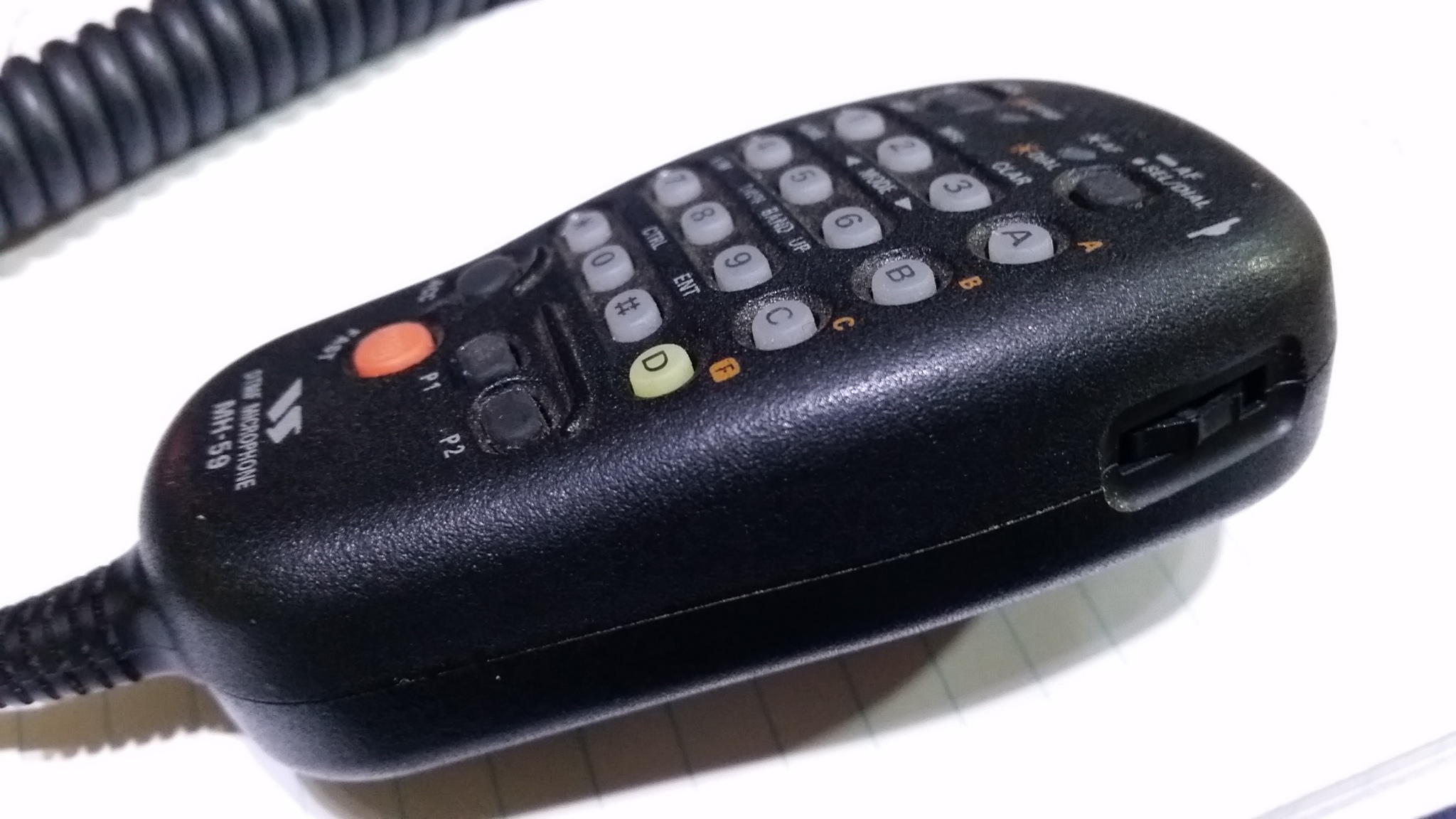
MH-59 A8J DTMF Microphone
Photos: © Copyright 2013-2017 Andrew VK1AD. All Rights Reserved
