Credits to John VK2ZOI (SK). John’s site is http://vk2zoi.com/articles/half-wave-flower-pot/
Post updates:
9 January 2016. Today from a SOTA peak (Yellow Rabbit Hill) 40 km west of Canberra using this antenna during a sporadic E opening, I worked ZL1SSW (2343 km) on 6m 50.130 MHz. My SOTA rig is a Yaesu FT-857D operating at 25 watts.
10 January 2017. Today from Mt Budawang using this antenna on 50.120 MHz with a FT-817 at 5 watts QRP I worked to radio amateurs in New Zealand, Dave ZL1AKW at Tauranga followed by Warren ZL1AIX near Auckland. 🙂
I have searched ‘ham’ radio publications and the internet for a lightweight, portable 6m 52 MHz antenna design suitable for SOTA activations. I found a terrific site by John VK2ZOI (SK) who constructed a vertical coaxial dipole named the ‘Flowerpot Antenna’ for obvious reasons. John’s design uses a single length of coax to form a choke and two 1/4 wave radiating elements forming a single 1/2 wave center fed vertical dipole. The purpose of the choke is to prevent common mode currents reaching the transceiver. The design is very simple and avoids mechanical joints, which can be an annoying point of failure particularly on a summit. With only one solder joint at the RF connector the likelihood of antenna failure is very low.
John’s design is perfect (IMHO) for use as a 6m SOTA antenna supported by a single squid pole or hung from a tree branch. I plan to coil ‘roll up’ the coax antenna for carriage in my backpack. I have no intention of enclosing the antenna in a plastic tube as one may do for a permanent installation.
Materials
- 10 metre length of Mil Spec RG58AU/CU
- Short length of 50 mm plastic pipe
- PL259 connector or your preferred RF connector of choice
- 2 small cable ties
I have no plans to enclose the antenna in a plastic tube therefore according to John’s notes each radiating element must be 3% (38 mm) longer than the length shown in his article. An interesting point is to compare the lengths specified by John against the formula for a 1/4 wave element at 52 MHz = 1370 mm long (300/52 x 0.95 x 0.25 = 1.37metres). You will note the bottom half (braid section) of the coaxial dipole antenna is considerably shorter than a 1/4 wave length most likely due the velocity factor of the cable.
Taking John’s figures and adding 38 mm to each element, the element lengths are:
- Top section (core of the coax) 1315 mm
- Bottom section (braid with plastic cover in place) 1255 mm
To start out I cut the top half element to 1.370 metres and after trimming the element for a low SWR, the 1/4 wave element is 1315 mm long. I didn’t alter the lower 1/4 wave element leaving the length at 1255 mm. Using a 13 turn choke the SWR is 1:1 at 52 MHz with a usable 1.5:1 range from 50.75 MHz to 53.5 MHz, perfect for use as a SOTA antenna on 50 and 52 MHz. If you plan to operate in the 50 MHz section of the band, then change the top section length to 1378 mm and the braid section length to 1343 mm. Leave the LC choke at 13 turns on a 50 mm diameter plastic pipe. See post update 20 November 2022 below.
VSWR plot: Antenna is mounted on a 7 metre squid pole and clear of metallic objects.

6m vertical Coaxial Dipole VSWR
Choke Self-Resonant Frequency
Choke calculations using 13 turns on a 50 mm dia former:
- D = 55 mm (cable center to center)
- N = 13 turns
- Length = 70 mm
- d = 4 mm (diameter of the shield)
- f = nominated frequency
http://hamwaves.com/antennas/inductance.html
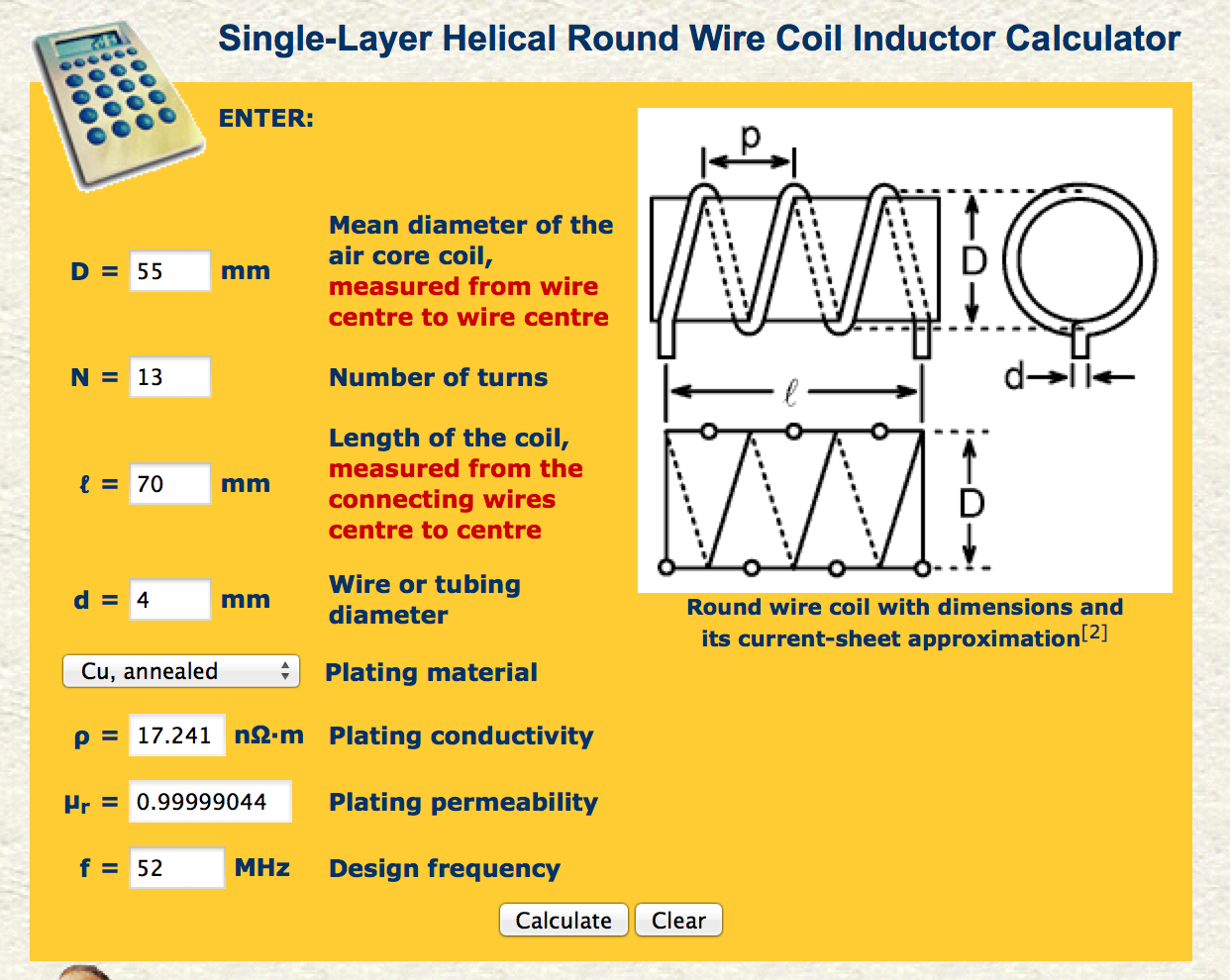
data for a 13 turn choke. 52 MHz is the nominated design frequency.

Self-resonant frequency
Construction
I purchased a 10 metre length of Mil Spec RG58CU from Watts Communications (Canberra). The type without aluminum foil.
1. Prepare one end of the plastic pipe by drilling one 6 mm hole in one end. Chamfer the hole to allow easy entry of the coax and reduce the stress of a severe right angle turn. (see John’s pictures). I used a tapered reamer to elongate the hole.
2. Coax cable. Start by removing 1350 mm of shield to expose the insulated core, be careful not to cut the insulation around the center wire. Trim the shield for a clean finish. Later place a 75 mm length of heat-shrink tube over the section to prevent moisture entry into the braid.
3. Next from the top of the braid measure 1255 mm down the coax. Mark this point with a permanent marker, use a colour you can see. At the marked point, place a short length of electrical tape around the coax. This marks the top of the choke or where the braid radiating element exits the choke. Do not cut anything!
4. Next, feed the coax through the center of the tube and out through the top hole and stop where you marked the coax with the electrical tape. Remember this is the start of the radiating element. Next wind 13 even turns of the coax around the 50 mm former, hand-pressure is enough when winding the turns. At the completion of the 13th even turn mark the plastic pipe and repeat the exercise in drilling and elongating the 2nd hole.
5. With the 2nd hole complete feed the remaining coax through the hole, gently remove any slack in the coil. The coax should exit the tube through the center of the tube. At each end of the tube use cable ties to secure the coax on the inside wall.
6. Next inspect the radiating elements for damage and double-check the length of each element. If all okay fix a RF connector (of your choice) to the end of the coax. I fitted a water-proof PL259. That’s it done!
Hoist the antenna up a non-metallic pole and check the SWR at the lowest frequency. I used a 7 metre squid pole. Check the VSWR and ‘trim’ the dipole top section to lower the VSWR (I reduced this section by 35 mm). If you cut too much off, you have the option to cut the cable ties and feed more coax through the former or solder a short length of wire to the existing core, and start again!
Please feel free to offer constructive feedback.
SOTA summits tests
On-air tests have shown the antenna performs well. From the summit of Mt McDonald, using a FT-817 and 5 watts output on 52.2 MHz SSB, I made contact with Gerard VK2IO on Mt Marulan, 105 km north. Our antennas were opposite in polarization, Gerard was using a horizontal dipole. Local VK1 and VK2 SOTA chasers those, within a 30 km radius were well received most with signal reports at 5-7 to 5-9.
What next, well I am now seeking interest from VK SOTA activators to attempt a 6m S2S contact using two vertically polarized antennas. I can wait for the summer sporadic E season.
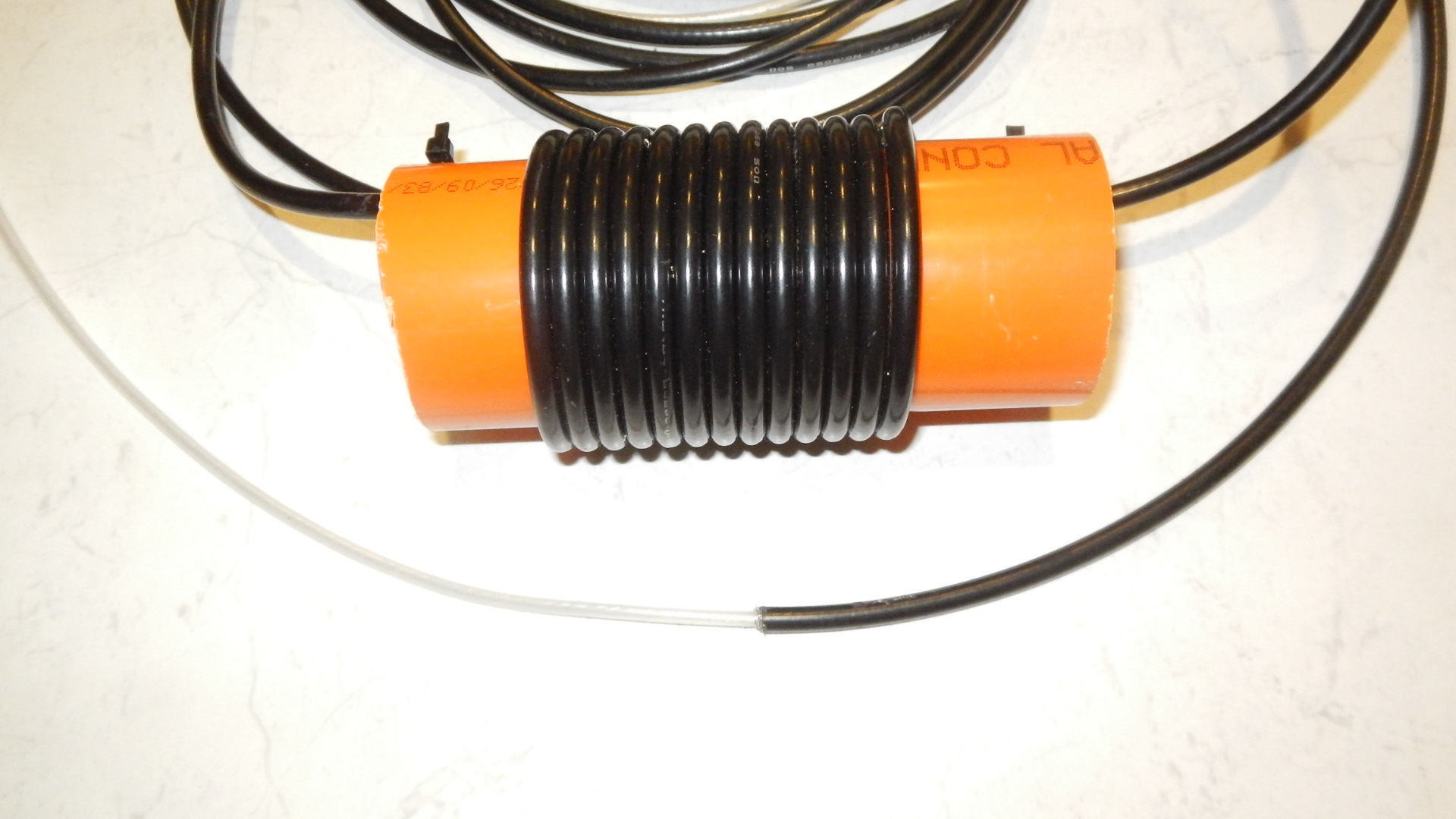
Construction photos
center of the antenna 1/4 wave elements. Do not connect the braid to the core. Overlay this section with a short length of heat-shrink tube.

tape marker to show the start of the radiating element at the top of the choke

completed antenna on the kitchen bench 🙂

6m Coaxial Dipole layout on the ground – ready to mount on a squid pole

RF Choke – mounted over the squid pole support

Top Section taped to the squid pole – coax core 1/4 wavelength (shield removed)
1/4 wavelength of shield above the choke (lower half section of the dipole)

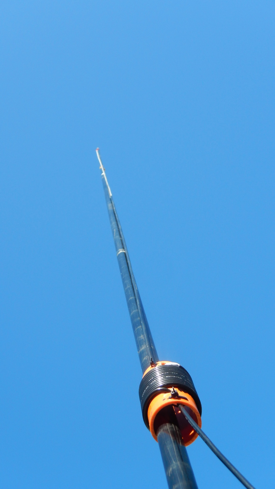
view of the choke mounted over the squid pole

Center frequency 52 MHz

6m coaxial dipole ready for the backpack
6m antenna in action on mountain peaks around Canberra

6m coaxial dipole on the summit of Booroomba Rocks VK1/AC-026 1382 metres ASL (16 Aug 15)

Mt McDonald VK1/AC-048 789 metres ASL (9 August 2015)

Spring Hill VK2/ST-036 876 metres ASL (8 January 2016)

Yellow Rabbit Hill 855 metres ASL – 9 January 2016
Page Update 20 November 2022
I have changed the dimensions of my 6m antenna for operation between 50.00 and 50.400 MHz. I plan to give 6m WSPR a go this summer. My preferred SOTA SSB frequency is 50.150 MHz.
For operation on 50.110 MHz change the element lengths to:
- Top section length 1378 mm
- Braid Section length 1343 mm
- Leave the LC choke at 13 turns on a 50 mm diameter section of plastic pipe
VSWR

Post Links:
- 9 January 2016 – 6m QSO with ZL1SSW
- 10 January 2017 – 6m QSOs at 5 watts with ZL1AKW at Tauranga followed by ZL1AIX near Auckland
Last update 16 January 2023


Great write up Andrew. I use a similar antenna in 2m from a design by Mark VK3ZR http://www.vic.wicen.org.au/?page_id=1353
I’ve never considered 6m as an activation band for SOTA and the simplicity of this antenna may just see me do it.
Pingback: SOTA 6m QRP – VK2 to ZL1 2340 km at 5 watts | Get out of the Radio Shack and Live Life
I was trying to scale this to another frequency and noticed this..
‘Compare the lengths against the formula for a 1/4 wave element at 52 MHz = 1350 mm long (300/52 x 0.95 x 0.25 = 1.35 metres).’
300/52 x 0.95 x 0.25 = 1.37 metres not, as you mentioned 1.35, so i’m a bit confused!!
I’m interested to know how you got to this figure as this is the only reference I can find to a formulae to work out the wave lengths I need; on any site including the original Post from VK2ZOI.
I’ve tried to alter the VF and the Freq. – but havn’t been able to match your measurements..
Hi Michael,
Definitely a typo, I am unsure why I have 1.35 when clearly the formula outcome is 1.37, I will correct the page. The formula has no relationship to the design, other than being a reference point for a 1/4 wave element. I think the best option would be for me to remove it from the page, save the confusion 🙂
As to your question about the actual length of the antenna elements, I copied John’s design noting that each element will be 3% longer. Antennas can be scaled, what frequency you are interested in?
Andrew VK1AD
If i’m honest, i’m looking at the 3m band, trying to see if they’ll be any notable differences between a flower over a standard dipole as a local community station has been looking to replace their Dipole with something that might fill a few nulls.
I use the same formulae for all my antenna design for a quarter wave, I was just confused as to how you got to that end result.
A great write up by the way, alot more in depth than other i’ve read..
Okay, how about scaling my antenna measurements by 0.52 (52/100) assuming 100 MHz is the center frequency?
Pingback: SOTA 2016 – VK1AD portable 70cm update #4 and Sporadic E | Get out of the Radio Shack and Live Life
Pingback: SOTA – Snowy Mountains Saturday 23 January 2016 | Get out of the Radio Shack and Live Life
Pingback: Mt Vinegar VK3/VC-005 Again | VK3YY
Pingback: Mt. St. Phillack – VK3/VT-006 September 2015 | VK3YY
Hi Andrew, I made the antenna today, didn’t take very long and was close to frequency first time. I had to add 50mm to the inner coax to have it resonating mid 52MHz. The SWR is fine from 52-53MHz. Cheers
Hi Glenn, thanks for passing on the info, 50mm is a fair variation though. I note in John’s design he has a variation of 30mm in the lengths of the two 1/4 wave elements with the top inner section being 30mm longer than the braid section. Did you try a 12 turn choke or stick with 13 turns?
Andrew
Hi Andrew, I stuck with 13 turns. My coax was not the highest quality stuff though, that might account for the variation.
Great writeup, Andrew. That calculator will be useful for designing my own common mode chokes. I’m tempted to build a coaxial dipole for 10m, for the next leg of the 6,/10m challenge. Thanks!
Nice article Andrew. I too think this is something for my workshop when I get back home. I think it’ll be SO much better than the rubber duck antenna I have been using for 6m on the 817.
Hi Andrew
After catching up with you in Canberra I built a 6 metre dipole for portable use. I had a contact in the mid-north with Ian, VK5CZ. Paul, David and I activated the Devil’s Peak (VK5/NE-080). It works well. I can now see another construction project on the horizon. It is a great design and I will check out your source (inspiration) as well. It should work well with FM as well (vertically polarised by ‘gentlemen’s’ agreement.
Cheers
John D
VK5BJE
Thanks for the very detailed article Andrew, I think I will give the antenna a try. How do the think RG714U 50 Ohm coax would work?? Cheers, Garry VK2GAZ
Hi Garry, I wonder if the smaller diameter coax will support the weight of the choke? The coil dimensions will have to be adapted to the smaller diameter coax. Plug the RG174 braid diameter and the spacing between turns into the coil calculator and check the self-resonant frequency. Trimming the shield away from the core will be interesting. Good luck!
A comprehensive write-up here Andrew, very nice. Thanks for sharing.