Like many in the amateur radio hobby, I have an interest in listening to my local airport air traffic and en route air traffic operating between Sydney – Canberra – Melbourne centres.
I am fortunate that my QTH is located in a RF line-of-sight path to Canberra International Airport (13 km east) and an air navigation repeater site 35 km south-east at 1730 m ASL. My Rx only equipment includes a RTL-SDR, an Icom IC-R20 and a Uniden 92XLT receiver, each fitted with a BNC mount 1/4 wave telescopic whip antenna. Other options include my Yaesu FT-817 or FT-857D as a VHF airband receiver.
For the most part air traffic and control tower signal strengths are good at S5 to S8, however there are one or two regional channels where signals are quite weak, which I describe as ‘in-the-noise’. I don’t need an external mounted antenna such as a wideband Discone, a Collinear or a half-wave Coaxial vertical, however a lightweight half-wave dipole would do the trick.
Local and regional air traffic frequencies (MHz):
- Canberra Tower – 118.700
- Canberra Ground – 121.700
- Canberra Approach – 124.500
- Canberra Departures – 125.900
- Canberra Terminal Weather – 127.450
- Wagga Wagga Tower – 118.200
- Albury Tower – 123.250
- Area 21 – 124.100
- En route to Melbourne – 132.200
- En route to Sydney – 128.400
- Sydney Approach (south) – 128.300
The aim of this post is to share the construction and assembly of an indoor airband half-wave dipole antenna. I am using the same design as I did for my 2m 145 MHz half-wave dipole. In this case the antenna design is centered on 125 MHz, therefore each element is 560 mm long.
Antenna Dimensions
| Frequency (MHz) | 1/2 wave * 0.95 | 1/4 wave * 0.95 |
| 118 | 1207 mm | 603 mm |
| 125 | 1120 mm | 560 mm |
| 136 | 1047 mm | 523 mm |
Diagram
125 MHz half-wave dipole antenna

Materials
- 2 * telescopic antennas, 7 sections 750 mm (28 inches) long with M2.5 holes (see pics). The mounting hole will determine your selection of screw sizes.
- 1 * section of kitchen cutting board 30 mm x 55 mm
- 1 * BNC panel socket with M2.5 mm holes
- 4 * M2.5 12 mm long machine screws
- 2 * M2.5 lock nuts
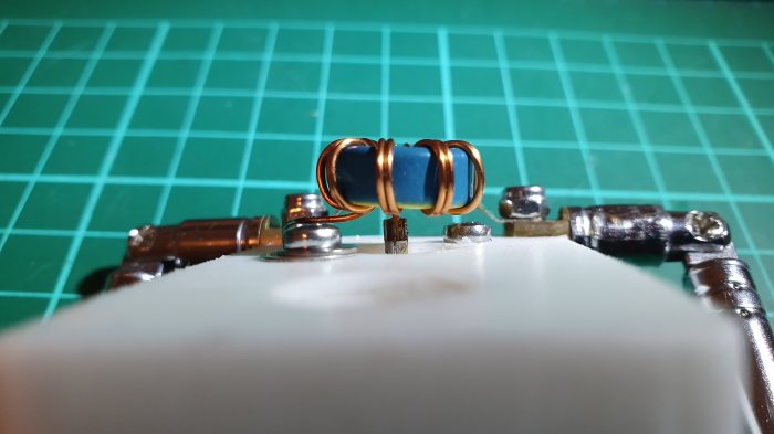
- 1 * T50-17 mix (Blue/Yellow) 12.8 mm toroid. 17 mix: 20 to 200 MHz
- 2 * 300 mm (12 inch) lengths of 20 AWG enamelled copper wire
- 3 * solder tabs
Toroid Choke – T50-17


Hang the antenna in your shack from a wall mount, in the roof space or by some other method you find appropriate. 🙂 For Rx purposes, I will use a short length of 50 ohm RG-174 coax to the receiver.
This antenna works equally well on 2m 146 MHz, adjust each element length to 485 mm. For low power QRP portable field/SOTA work you can mount the antenna on a telescopic pole or hang it from a tree branch. Each element can be rotated in the horizontal or vertical plane to match the receiving station antenna polarisation.
Last update: 4 December 2019


