2m Slim Jim portable antenna for SOTA
The success of 2m HT contacts will generally be based on the quality of the HT antenna, which in most cases is a base loaded 1/4 wave. So how do you improve the quality of your signal when using a HT? You can buy expensive after-market products based on a 19 inch 1/4 wave antenna or you can make your own antenna. If you chose to make your own antenna there are factors you should consider such as weight, storage in your pack, durability, ease of deployment and mounting arrangements.
Having considered all of the issues, I decided to make a Slim Jim vertical. The Slim Jim design is based around two parallel wires, which immediately brings to mind 300 ohm TV feed line or perhaps 450 ohm ladder line and this is where durability will be a consideration.
I chose to build the antenna from a single length of 450 ohm ladder line where the wire is single core copper coated steel and sufficiently flexible to roll up, deploy and re-pack . If you are thinking of using 300 ohm TV line then consider the durability of the thin copper wire, solder joints and the UV rating of the plastic. 450 ohm ladder line is tough, UV resistant and sufficiently flexible to roll into a manageable package thats sits in the top section of my pack. I purchased the ladder line from the US, there are well-known dealers in Melbourne and Sydney who stock 450 ohm ladder line.
Photos: © Copyright 2013-2017 Andrew VK1AD. All Rights Reserved
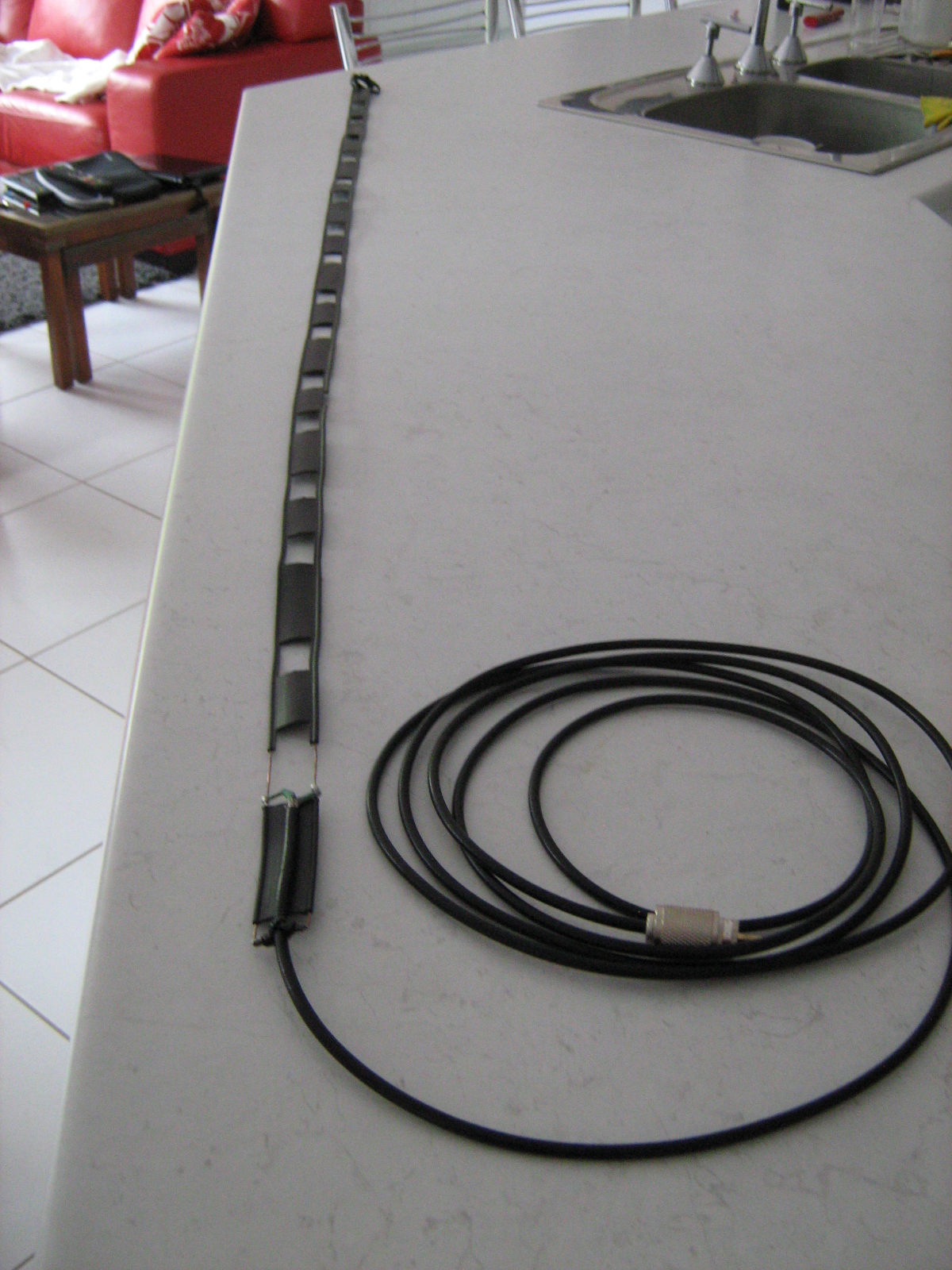
2m Slim Jim
Okay I have the 450 ohm feed line, what next? Go to the website of John M0UKD and select the Slim Jim from the Calculator menu.
Enter the design frequency (I chose 145.00 MHz as I want the ability to work 144.200 SSB and 146.500 FM) and select calculate. John has used a default spacing of 45 mm between the two parallel wires.
In my case the antenna dimensions using 450 ladder line with a spacing of 21 mm are as follows:
(A) Overall length: 1507 mm, make allowances for extra wire to fold and solder at the ends
(B) 1/2 wave phasing element (B): 991 mm from the top down
(C) 1/4 wave match: 493 mm
(D) Feed point 85 mm from the bottom
(E) Notch: 23 mm space between B and C
(F) Spacing between elements: 21mm
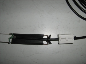
The antenna has two solder joints, the top and bottom sections. The coax is soldered directly to the copper coated wire. The coax center conductor is soldered to element A while the braid is soldered to element C. I used heat shrink to add some protection to the exposed coax.
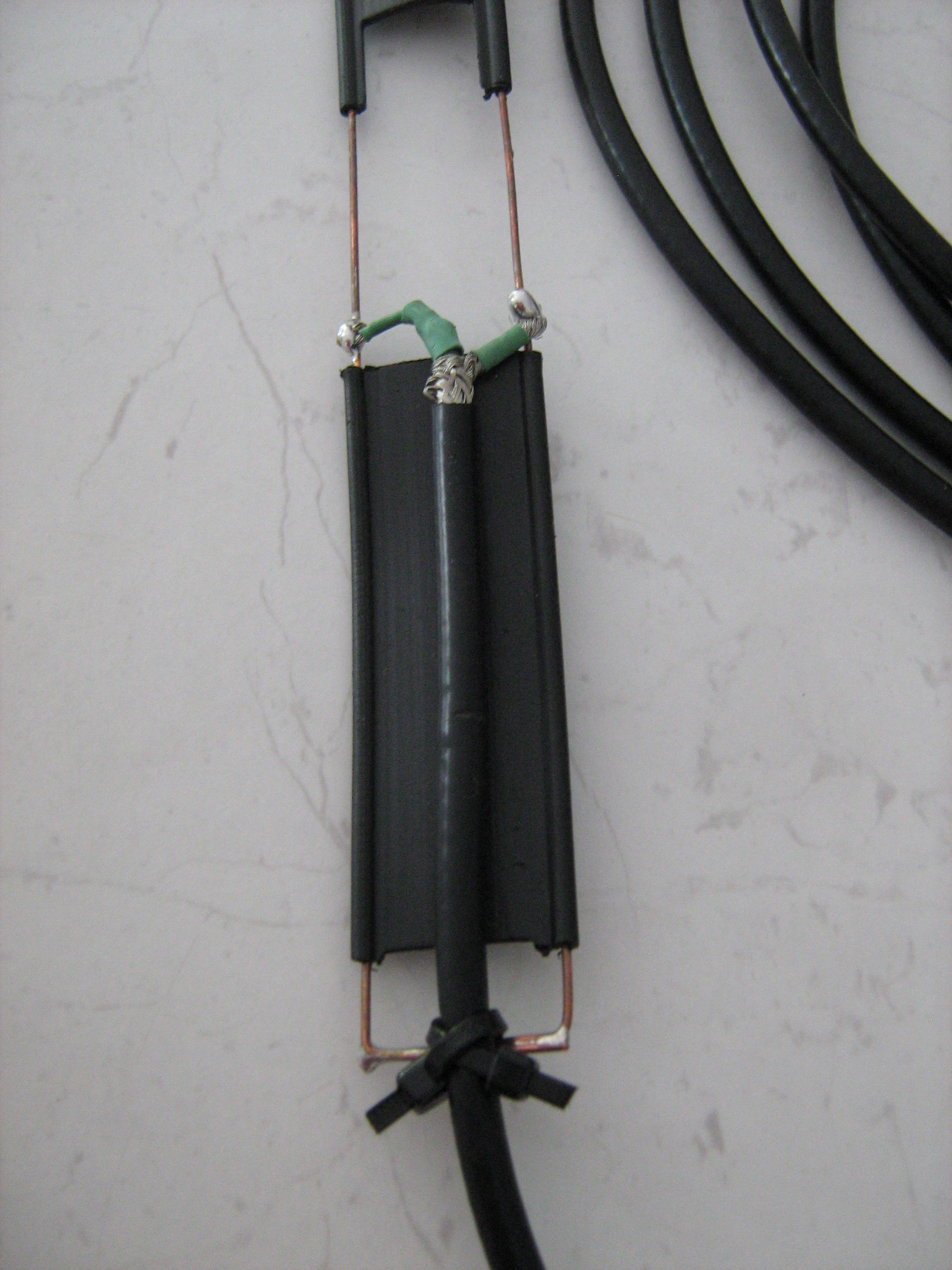
Slim Jim feed point note the bottom section is joined
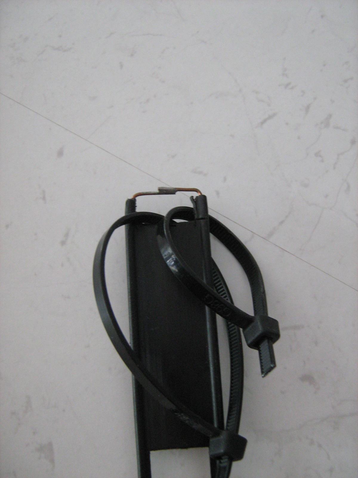
Top ends are soldered. To support the antenna on a squid pole I have used cable ties to slip over the end of the pole. You can experiment with the height by changing the cable tie diameter. In the event you can’t use a squid pole try hanging the antenna from a tree branch
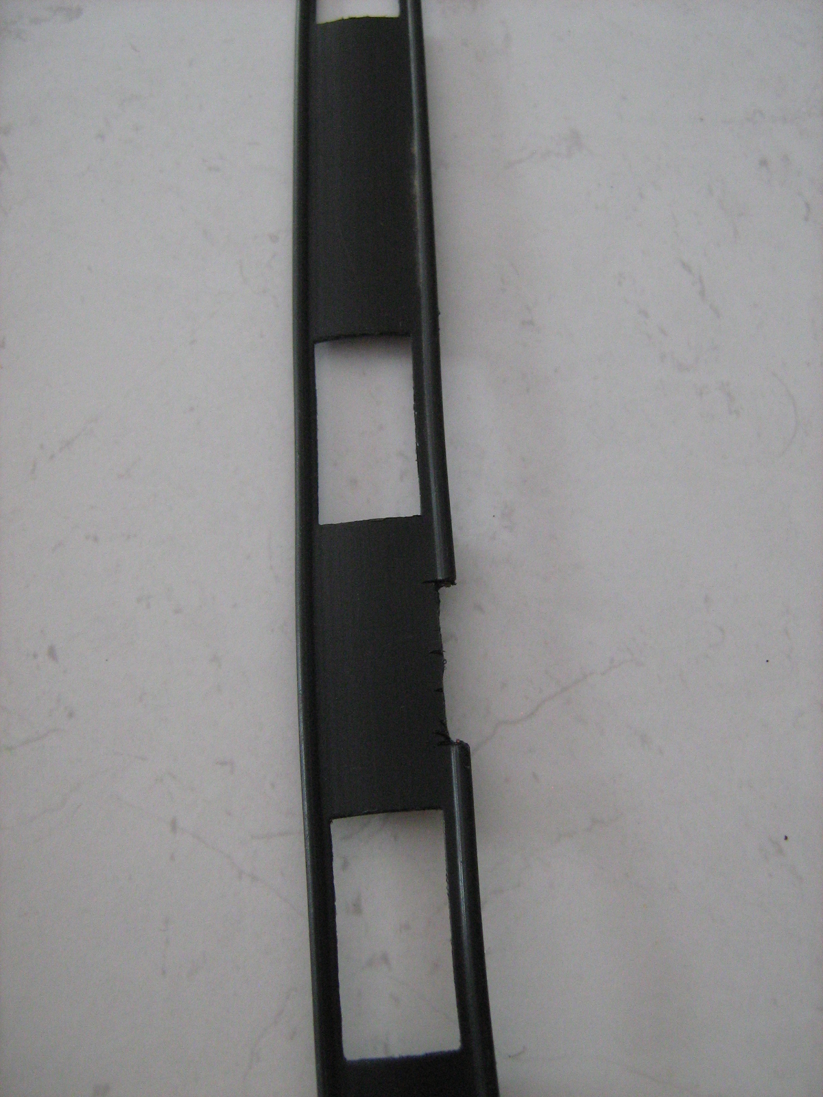
Notch separating the phasing element from the 1/4 wave match
The coax cable is supported at the bottom joint by two cable ties overlapping each other. This reduces the stress on the solder joints. When you first attach the cable ties leave some slack so the coax can be moved while tuning.
To tune the antenna attach the coax center and braid to the elements. Using low power check the SWR. Move the feed point up or down the elements until you get a low SWR. You may need to remove some of the plastic spacer between the elements. Once you have obtained a low SWR tighten the cable ties to prevent the coax from moving and solder the joints. The length of coax is not a design factor, I use 4 meters of RG58AU (MILSPEC) sufficient to elevate the antenna on the squid pole.
The design of the Slim Jim is an end fed folded dipole which produces an efficient vertical polarised signal at around 6 degrees above the horizon. The antenna is 3/4 of a wave length long but operates as two 1/2 waves in phase. For analysis of the antenna see VK3WAM’s post where Wayne used a MiniVNA Pro on the Slim Jim. (scroll to the bottom of the post). If you have the inclination, enter the antenna measurements in MMANA-GAL and check the plot.
I have installed a single ferrite choke clamp 20mm below the bottom of the antenna to prevent feed line radiation. You can mount the antenna on a squid pole or hang it from a tree branch. If you are using a metal structure such as trig ensure the antenna is at least a 1/2 wave length away from the steel post. If you are looking for a permanent mounting you can mount the antenna in a length of plastic conduit and seal both ends.
Ferrite choke

2m Slim Jim deployed on VK1/AC-039

2m Slim Jim supported by a tree branch on Nursery Hill VK1/AC-022
Have fun building the antenna, you will be surprised by its performance.
70cm Slim Jim

70cm Slim Jim

70cm Slim Jim

Pingback: SOTA – Riley’s Mountain Blue Mountains National Park | Get out of the Radio Shack and Live Life
Hi Andrew,
How did you get the 81mm for D? When I use the calculator it gives 49mm. I get the same measurements for everything else!
Thanks
Scott
Vk2AET
Hi Scott, The value of D is a start point for you to connect the coax. You have to move the feedpoint up or down the parallel wires to obtain a low VSWR. I found a low VSWR at 81mm from the bottom. You will have to remove a section of the plastic to expose the parallel lines.
Pingback: South Black Range VK2/ST-006 – 22 September 2013 | Get out of the Radio Shack and Live Life
Pingback: Castle Hill VK1/AC-032 – 11 August 2013 | VK1NAM Summits on the Air (SOTA)
Pingback: SOTA Activation Spring Hill – 1 December 2013 | VK1NAM Summits on the Air (SOTA)
Pingback: South Black Range VK2/ST-006 – 22 September 2013 | VK1NAM Summits on the Air
Pingback: Two summits Sunday 24 km hike – 25 August 2013 | VK1NAM Summits on the Air
Pingback: Castle Hill VK1/AC-032 – 11 August 2013 | VK1NAM Summits on the Air