I’m enjoying the challenge of 23cm 1296 MHz homebrew antenna construction for SOTA purposes. My 23cm portable antenna collection includes:
- 12el DL6WU Yagi 12dB gain – lightweight boom construction using a folded dipole;
- 6el DL6WU Yagi 9 dB gain – ruggedised all brass construction gamma matched, ideal for the Australian scrub bash; and
- 2el HB9CV Yagi 4 dB gain – all brass construction, useful lightweight option for local summits around Canberra.
23cm Bi-Quad Antenna
This post demonstrates the method to constructing a 23cm Bi-Quad antenna which I plan to use for SOTA activations. The Bi-Quad is also known as a double-quad antenna. Whilst I haven’t modelled the Bi-Quad against my 6el yagi, I understand the Bi-Quad gain is around 9 dB with a 60 degree beam width, happy to be corrected. All dimensions are in millimetres (mm).
Materials:
-
- SMA female socket to RG-402 (solder type)
- 55 mm length of RG-402 semi-rigid copper shield coax. Outer diameter 3.6 mm
- Double sided copper clad PCB
- 500 mm length of 2 mm copper wire (junk box)
- 2 * 32 mm stand-off insulators. I used 7 mm diameter plastic sprinkler riser tube
- 2 Cable ties
- Solder
- PCB enamel
23cm Bi-Quad antenna dimensions
Varying the space between the driven element and the reflector surface changes the antenna feed point impedance. Although the calculator shown below specifies a spacing of 29 mm, I found a spacing of 32 mm produced the lowest VSWR at 1.1:1.
For dimensions see: Changpuak Bi-Quad online calculator
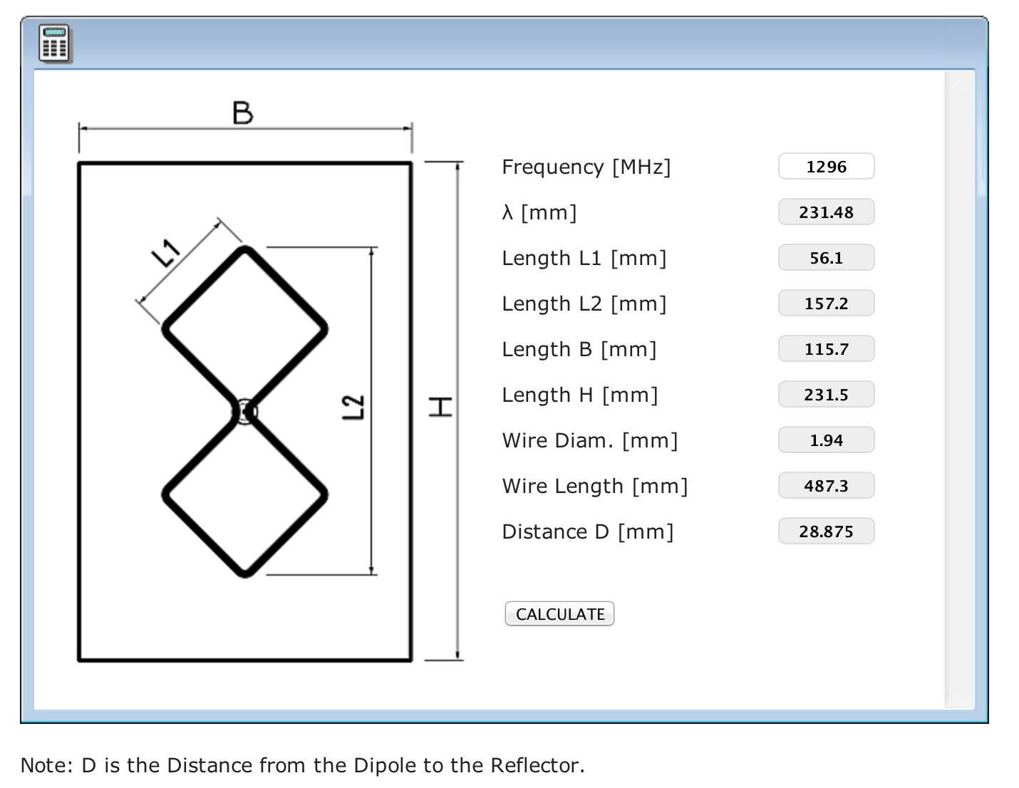
23cm Bi-Quad Antenna Dimensions – courtesy of changpuak.ch
Method
Start with a blank double sided PCB 300 x 250 mm. Mark out a rectangle 231 x 116 mm to form the antenna reflector.

Double sided PCB – antenna reflector marked out 231 x 116 mm
Reflector cut to size 231 x 116 mm. Drill a 2 mm hole in the center of the reflector.

Mark out the center of the reflector and drill a 2 mm pilot hole.
RG-402 3.6 mm semi-rigid feed line and SMA connector assembly

Trim the RG-402 coax to expose the center conductor
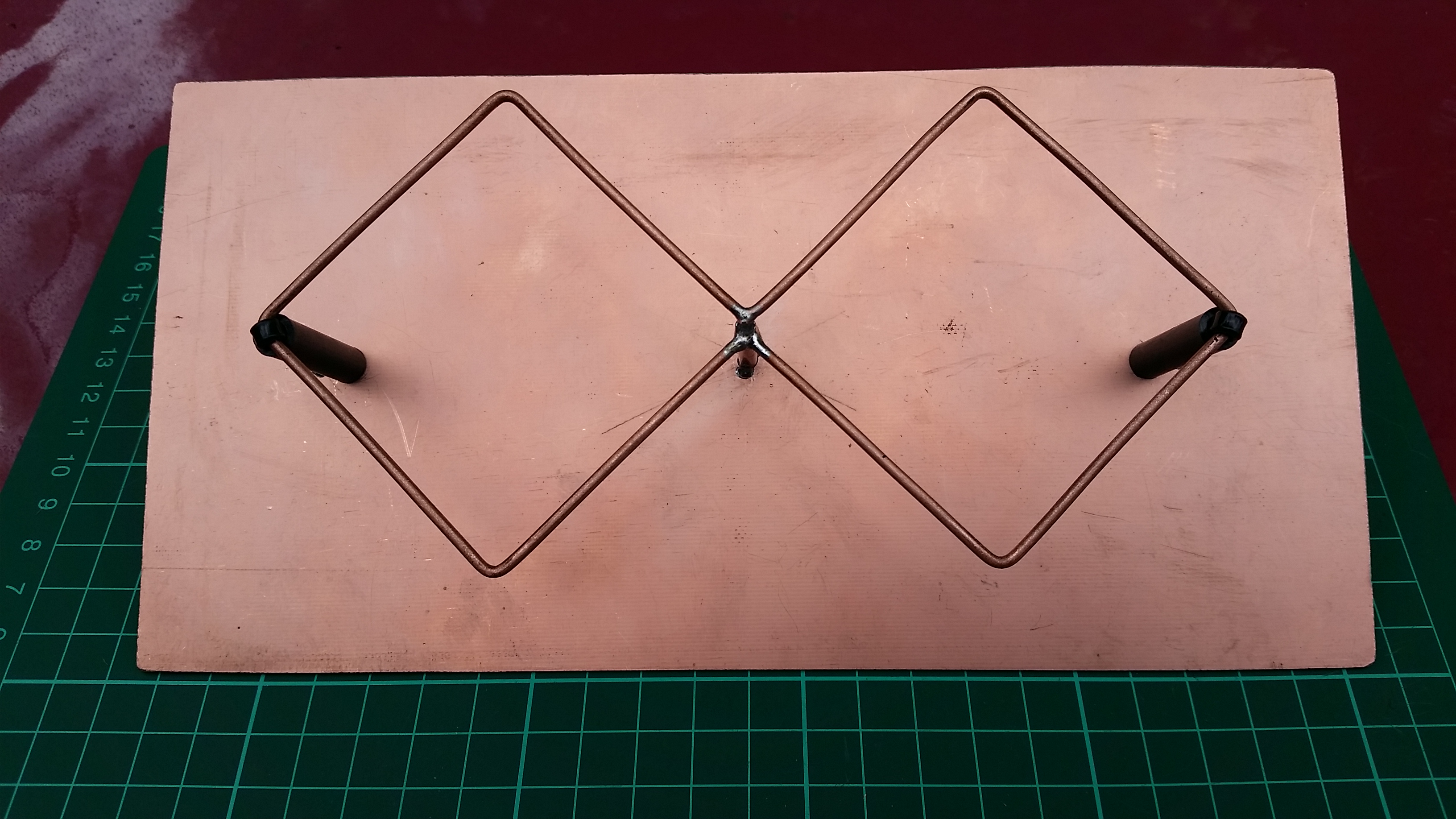
Driven element
I had on-hand a 500 mm length of 2 mm copper wire found in the junk box. Fold the wire at right angles to produce two 56 mm quads, remove any excess wire. The center fold of the two quads forms the antenna feed point. The two open wire ends are soldered to the RG-402 copper shield. I will use emery paper to remove the build up of oxides. Once construction is complete I will spray the assembled antenna with a light coat of non-conductive PCB enamel.

Bi-Quad driven element with wire ends meeting in the middle
Drill the reflector center hole (3.5 mm) or use a taper ream to match the outer diameter of the coax, you should aim for an interference fit. You may have other ideas or options on your choice of coax. 🙂

Driven element cleaned with emery paper
Feed line SMA Connector
Prepare the RG-402 for the female SMA connector


Assembly
In the next picture the driven element is positioned before soldering, you will need a spare pair of steady hands! Before soldering make sure the spacing between the quad ends and the reflector surface are the same. The driven element must be parallel to the reflector surface. Be patient this step is fiddly 🙂

Position the center of the driven element for soldering to the coax center conductor
The picture below demonstrates the center of the folded Bi-Quad is soldered to the coax center conductor. The two open ends are each soldered to the shield.

Driven element soldered in place
Test for 50 ohm Impedance
At this stage connect the Bi-Quad antenna to a suitable VSWR meter and a low power 23cm transmitter or if you have one a microwave antenna analyser. To find the lowest VSWR reading slide the driven element assembly through the reflector center hole. In my case the lowest VSWR reading corresponded with a spacing of 32 mm.
Next cut two 32 mm lengths of sprinkler riser tube to form two stand-off insulators, test a trim the length as required. Drill two holes in the reflector to align with the quad ends. See my pencil markings on the reflector surface.
Mount the stand-off insulators and secure the driven element ends with cable ties. Next check the VSWR reading a second time. If the VSWR hasn’t changed solder the RG-402 copper shield to the reflector surface. Repeat on rear side where the shield extends through the hole.

View of the driven element and coax feed line. Driven element ends are supported by plastic stand-off insulators
You have the option to mount the SMA connector flush with the PCB, I chose to extend the feed line though the board by 20 mm. The space behind the reflector offers options for portable mounting. For permanent outdoor mounting arrangements, you may like to enclose the antenna in a UV resistant plastic box.
23cm Bi-Quad antenna assembly finished!

23cm Bi-Quad assembly side view
23cm Bi-Quad assembly top down view
Thanks for reading this post. Good luck with your 23cm antenna construction 🙂
Post update – Thursday 28 December 2017, I used this antenna from SOTA peak VK2/ST-005 Webbs Ridge @ 1308 m ASL heavily wooded by Eucalypt and Wattle trees. With the help of Matt VK1MA located in Canberra at a distance 24 km (shadowed by a 1200 metre mountain peak) this antenna produced a 1 S-point difference over my 6el brass yagi, signal report was 5-8. I know the test is subject to all sorts of variances including the density of the local bush scrub, rugged terrain and the potential for signal path changes, however it was useful for me to test the Bi-Quad antenna in a real world scenario. I’m very happy with the outcome, it passed the Aussie Bush Scrub test!
The photos below demonstrate the density of the bush scrub on mountain peaks around Canberra. We have very few green rolling hills free of obstruction. 😉


When I have the opportunity I will test the antenna along a point-to-point signal path between two distant peaks free from terrain obstructions.
My next challenge is to design and build a bracket for mounting on a camera tripod.
If you are interested in a homebrew 13cm (2.4 GHz) Bi-Quad antenna select this link.
Photos and drawings: © Copyright 2017 Andrew VK1AD
Published: 27 December 2017
Last Update: 24 February 2018


Pingback: 23 CM Homebrew Antenna For SOTA Purposes | Coastal Ham Radio
Pingback: 23cm Transverter – Tripod Platform and Bi-Quad Antenna Mount | VK1 SOTA on 1296 MHz