VK1AD 23cm (1.296 GHz) 6el Yagi – Construction of a rugged solid brass DL6WU yagi ready for the SOTA backpack!
My collection of 23cm SOTA antennas includes two DL6WU homebrew folded dipole yagis, 6 and 12 elements. While both antennas offer excellent gain, their lightweight design means they are limited to summits with limited scrub bashing, clear walking trails or 4WD tracks. Entanglement of the antenna’s folded dipole with the Australian scrub may damage the driven element rendering the antenna inoperable.
I need a rugged 23cm yagi suitable for scrub bashing, something that will withstand the interior of my backpack but also one that offers reasonable gain. I have two PCB 23cm yagi antennas; a 2el HB9CV and a 3el WA5VJB which work well for suburban and local Summit to Summit (S2S) contacts or for 100 km signal paths with limited obstructions.
My friend and SOTA companion Andrew VK1DA/VK2UH has a solid brass 4el 23cm yagi which has ‘even’ spacings between the driven and two director elements. To my surprise his antenna incorporates a gamma match for 50 ohm impedance matching. Having seen Andrew’s ‘all-brass’ 23cm yagi I am confident I can draw upon my former trade ‘fitter and turner‘ skills to build a 6el DL6WU variant.
Materials:
- 1 * 6 mm square brass bar – 300 mm;
- 6 * 120 mm lengths of 3 mm brass rod;
- 1 * Female SMA panel mount, 4 holes;
- 1 * 0.8 to 6 pf ceramic piston trimmer capacitor, 5.3 mm dia * 20 mm long. Look for a version with solder lugs.
- 2 * M2.5 mm by 8 mm brass screws; and
- Solder.
Tools:
- Vernier caliper (150 mm), digital or analogue
- Machine Square or Engineer’s Square
- 150 mm steel rule
- Pedestal Drill
- 1 mm, 2mm and 3 mm drill bits
- Set of M2.5 * 0.45 pitch thread taps
- Adjustable Tap Handle
- Countersink drill bit
- Scriber
- Center Punch
- Hand File fine-cut
- Needle File fine-cut
- Hacksaw
- Hammer
- Butane torch
- 20 watt solering iron
- Microwave SWR meter
Method
- Mark out a center line along the length of the brass 6 mm square boom. I used a woodworker’s Marking Gauge to scribe the line.
- Using a sharp Scriber and the Engineer’s Square, mark out the center line for each element R, DE, D1, D2, D3 and D4. Where the element’s center line intersects the boom center line, mark the intersection by applying pressure to the tip of the scribe making a small sharp impression in the brass boom.
- With a sharp centre punch mark the center position of each element. Take care in placing the center punch in the small impression. Start with a light tap of the center punch and check the position of the mark. Tap the center punch a second time, don’t hit the punch too hard otherwise the impact will bend the brass boom. Run your eye down the length of the boom or use the Engineer’s Square to check the bar is straight.
- Now, don’t get ahead of yourself, I know you are eager to drill holes in the boom, instead take a deep breath and revisit all of your measurements, marking out and punch marks. Measure twice and drill once! If you have made a mistake, turn the boom over to a clean face and mark out again. 😉
- Confident you have correctly marked out each element’s position, with a 1 mm drill bit, drill the element pilot holes. Check the spacing between pilot holes.
- Finish each hole using a 3 mm drill bit. Yes, you are correct a 3 mm hole will not produce and ‘interference fit’, that will come later. Take a length of 3 mm brass rod, insert the rod into the hole and check the element is sitting at 90 degrees to the boom. If the element is slightly off 90 degrees don’t worry.
- Next chamfer the holes on each face of the boom. The chamfer will form part of the boom/element solder joint.
- Put the boom in a safe place, we will come back to the boom.
- Next starting with the Reflector and working to DE, D1, D2, D3 and D4, cut each element to length. With the scriber and a 150 mm steel rule, mark out each element, deliberately add 1 mm to the element length. Double check your markings (element length + 1 mm). Secure the brass rod in a bench vice and make a clean-cut through the brass rod. Debur the brass rod and measure using a Vernier caliper.
- Using light file strokes, file one end of the brass rod and recheck the element length. Keep filing until the element length is within 0.01 mm. Lightly debur the end with a 45 degree chamfer. If like me you filed too much material off one end, use the element for the next shortest.
- With all elements cut to length double-check their lengths.
- Next place the boom on the workbench or on top of the bench vice, you need a flat surface to work on. You are going to ‘score’ the edge of each element hole. Check the photo below. You can see a small center punch mark within 1 mm of the hole.
- Place the sharp centre punch close to the edge of the hole and strike the punch very lightly with a hammer. The aim is to make a slight distortion to the edge of the hole. This will form an ‘interference’ fit for the element. Repeat this process for each hole.
- Check the boom is straight.
- Starting with the Reflector, place the element in the opposite face to the punch mark. Lightly tap the element through the hole. If the punch mark didn’t produce the required interference fit, remove the element and mark the opposite side of the hole. In the photo you can see small punch marks either side of the element hole.
- Lightly tap each element into the boom, roughly half way. You can use the 150 mm steel rule to measure each side of the element. With all elements in place recheck the boom is straight.
- Starting with the Reflector take the Vernier caliper and measure each side of the element between the boom face and the element end. Lightly tap the longer side and remeasure. Work slowly until both sides of the element are equal with respect to the boom face. Repeat this process for all elements. Before soldering each element in place recheck with the Vernier caliper.
- Next, with all elements secured in the boom by the interference fit place one end of the boom in the bench vice.
- Using a butane torch, heat the boom evenly along the length of the boom, work quickly.
- Starting with the Reflector heat the element evenly, then apply heat directly to the area around the boom/reflector hole. Apply enough heat so that the solder will take evenly around the element into the chamfered hole. see photo below
- Turn the boom over and solder the opposite face. You will need to wear welding gloves 🙂 With both sides soldered check for an even distribution of solder around each hole.
- Next solder the driven element in place. Repeat this process for D1, D2, D3 and D4.
- Allow the boom to cool then clean up any excess solder with a small needle file.
- Once again, check each element’s dimensions either side of the boom.
- Next, starting with the reflector check both sides of the element are at 90 degrees to the boom. If the element is slightly off 90 degrees, lightly bend the brass rod. Check the opposite side. With the reflector at 90 degrees you can now measure the distance between the tips of each element.
- Take the Vernier caliper and check the spacing between the tips of the Reflector and DE. Measure both sides to make sure DE is parallel to the Reflector. For a rough check place the Engineer’s Square on the boom and check each element is at 90 degrees.
- Next check the tip spacing between DE and D1. Repeat for D2, D3 and D4.
- Well done you have finished the construction of a 23cm DL6WU yagi.
- Next you might like consider the mechanics of the feed point? I opted for a SMA combined gamma match.

VK1AD – 23cm yagi elements cut to length
I considered a range of connector types and finally settled on a female SMA panel mount.
Parts: SMA panel connector and Ceramic Piston Trimmer Capacitor

SMA panel mount and variable ceramic piston capacitor
M2.5 thread taps


Gamma Match
- Using a scriber mark the position of two panel mount holes.
- Use a center punch to mark the center of each hole then check the hole spacings.
- Drill both holes starting with a 1 mm pilot drill followed by a 2 mm drill bit.
- Tap both holes using a M2.5 * 0.45 mm pitch thread starting with a taper tap and finish with an intermediate and plug taps.
- Secure the SMA panel mount to the boom with two M2.5 * 8 mm brass screws.
- The only time you will use the solering iron, solder the ceramic piston capacitor rear solder lug to the SMA center pin.
- Trim the front lug for a center line spacing of 8 mm.
- Using a butane torch gently heat the DE then solder the lug in place.
- Remove any excess solder with a needle file
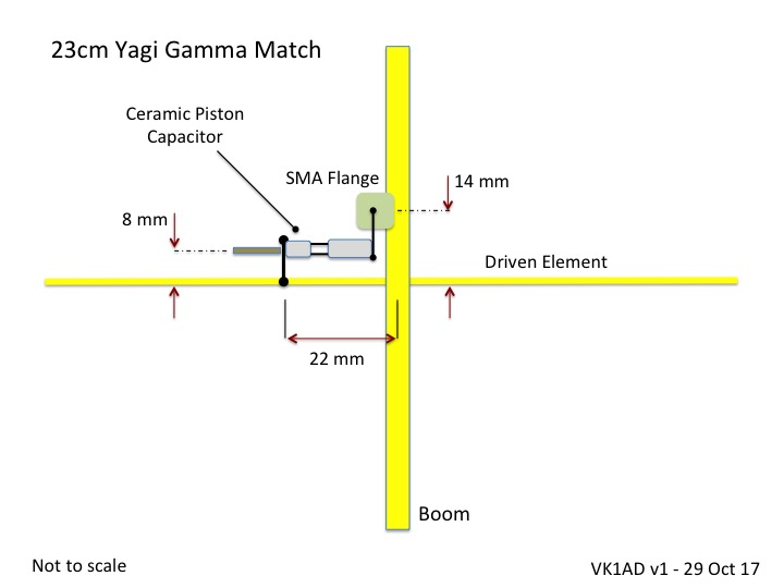
23cm Yagi Gamma Match
Antenna feed point and Gamma Match

Feed point – SMA flange secured to the boom by M2.5 mm brass screws
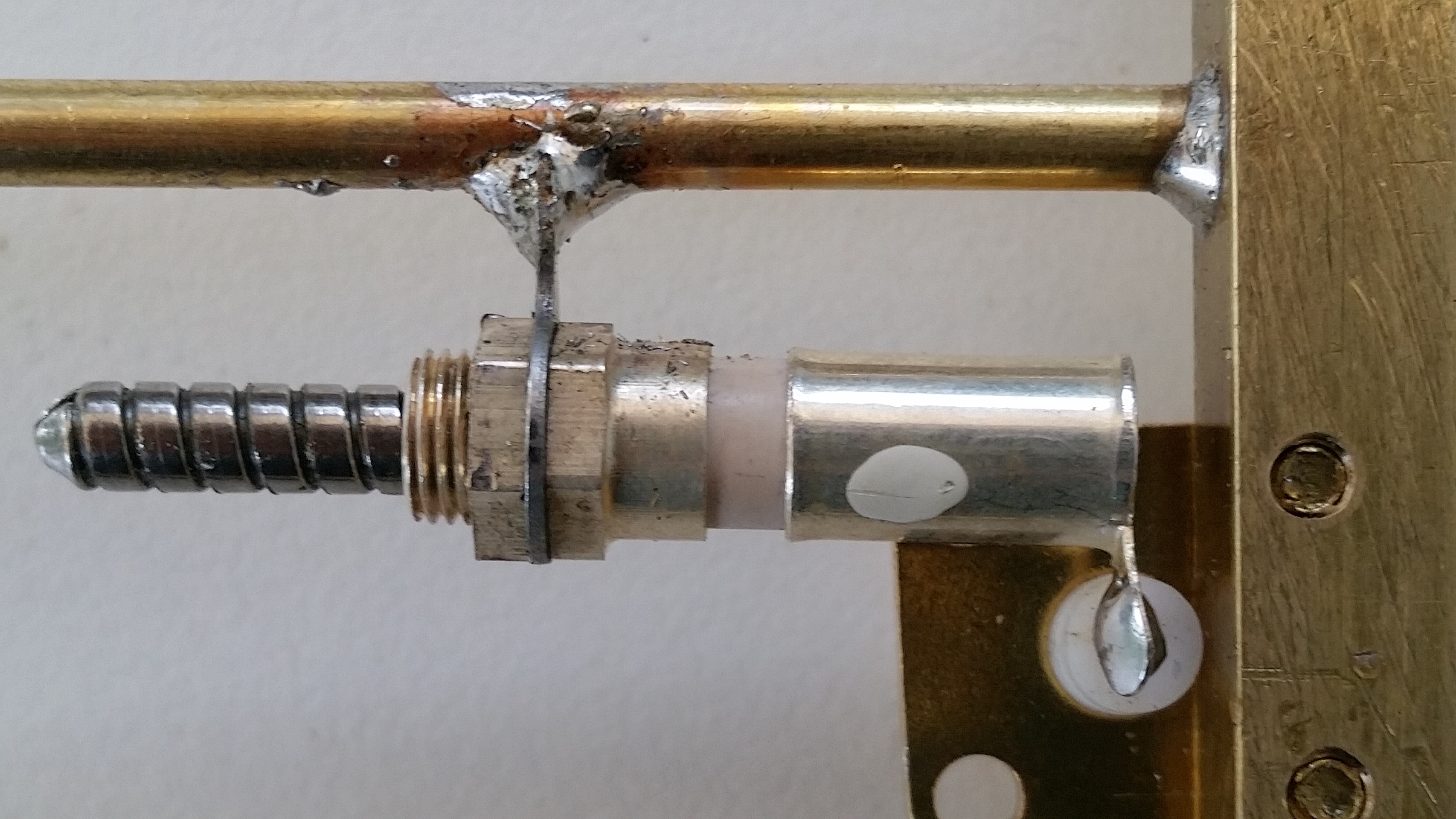
Gamma Match variable piston capacitor

Ceramic Piston Capacitor
50 ohm impedance match. Adjust the Ceramic Capacitor piston for a low SWR reading
SWR Meter – Forward Power from my SG-Lab 23cm transverter

SG-Lab 23cm Transverter – Forward Power reading 2.8 watts
Reflected Power

Reflected Power reading
The SG-Lab transverter incorporates a LED SWR indicator. On transmit (FM Carrier) the SWR LED display is ‘Green’

VK1AD – solid brass DL6WU 6el 23cm yagi
I’m now considering how I will mount the antenna, options include a tripod mount or to the side of a telescopic pole. The ‘handle’ section behind the reflector offers ample space for a range of mounting options.

VK5DJ Software – 23 cm DL6WU Yagi Element Lengths and Spacings
Weight

Yagi weighs in at 150 grams
What’s next, how about a homebrew 23cm HB9CV?
Thanks for reading this post. Good luck with your antenna construction 🙂
Photos and drawings: © Copyright 2017 Andrew VK1AD
Published: 29 October 2017
Last Update: 9 November 2017


Pingback: Construction of a 23cm 1296 MHz Bi-Quad Antenna | Get out of the Radio Shack and Live Life
not sure where to get the ceramic piston trimmer capacitor from – they don’t seem to have them in the UK. Looks like a well built antenna though.
eBay Bulgaria 🙂 search piston trimmer capacitor.
Cheers
Andrew
Reblogged this on Coastal Ham Radio.
Pingback: SOTA – Homebrew 23cm 12 element Yagi Antenna | Get out of the Radio Shack and Live Life
Terrific Andrew nice little build look forward to working you with it on your next outing
Cheer 73
Rod
VK2TWR
Thanks Rod, I did hope to get out last Saturday but domestics had a priority. The Wx for next Saturday/Sunday is looking like rain. I would like to take a trip down your way to The Peak. Hope the Wx forecast changes for this coming weekend. Cheers Andrew.