Post updated 29 November 2020. Driven elements are now threaded with M3 thread and the center insulator is fitted with two M3 x 20 mm brass stand off nuts.
Portable 4 element 2m (145 MHz) DL6WU Yagi for SOTA weighing 460 grams (1 lb)
Materials:
- 4 metre length of 3.1 mm aluminium rod (Alucom)
- 1 metre length of 27 mm PVC water pipe
- 2 * plastic end caps
- 5 * 25 mm PPR plastic pipe clamps (ebay)
- 3 to 5 metres of RG58CU Mil Spec Coax. Length is your choice.
- 2 brass terminal connectors cut from a 10 amp terminal strip
- 8 cable ties
- Araldite
- Tripod quick release plate
Dimensions – 6.5 dB gain:

Antenna dimensions – 145 MHz 6.5 dB gain
For storage all elements fit inside the 27 mm boom. The driven element insulator will remain clamped to the boom. Combined weight is 460 grams (1 lb), (Antenna, Coax and Tripod Mount).
25 mm PPR pipe clamps
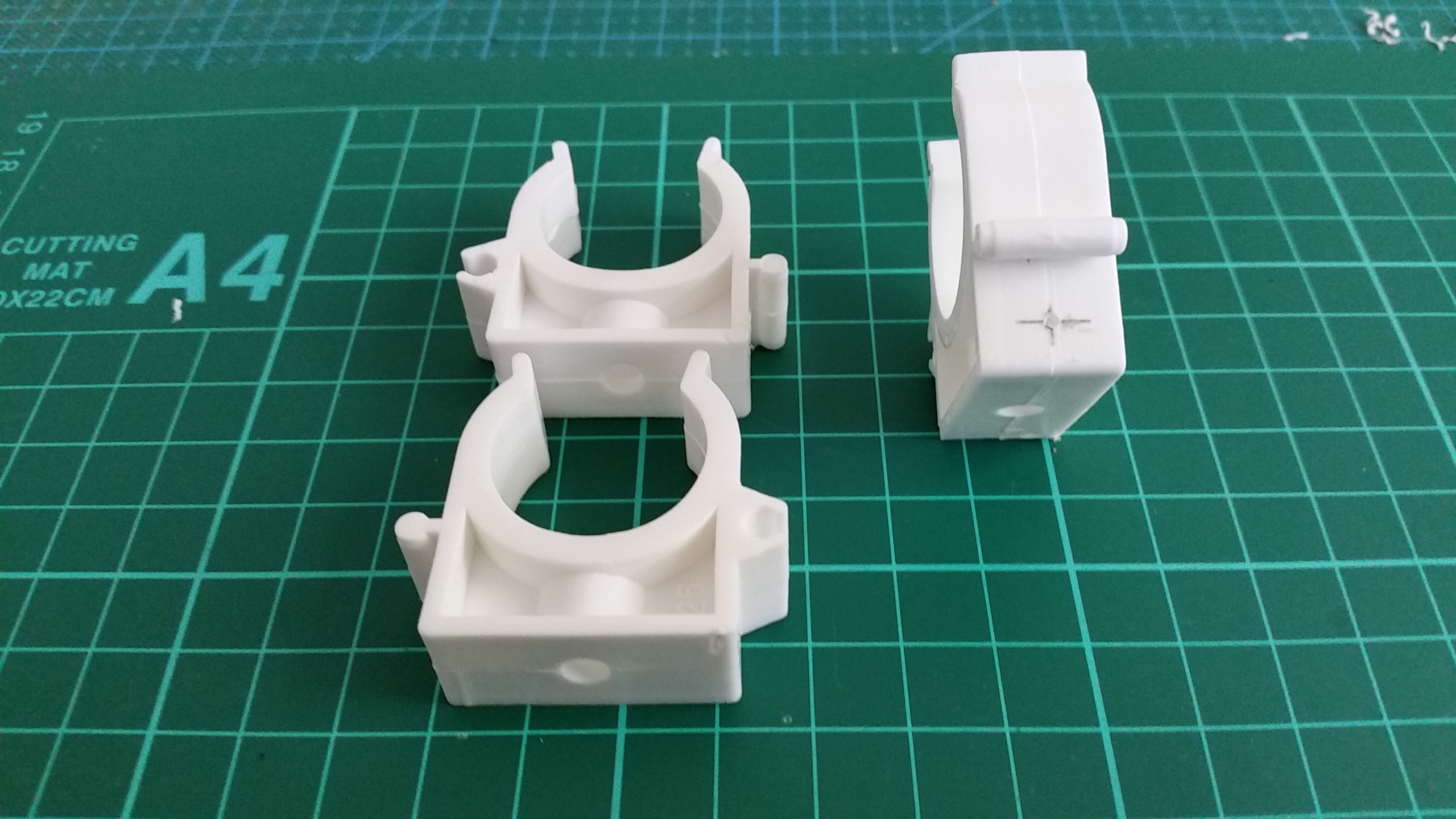
25 mm pipe clamps. Hole marking is 5 mm from the top of the clamp. Mark each side of the clamp.
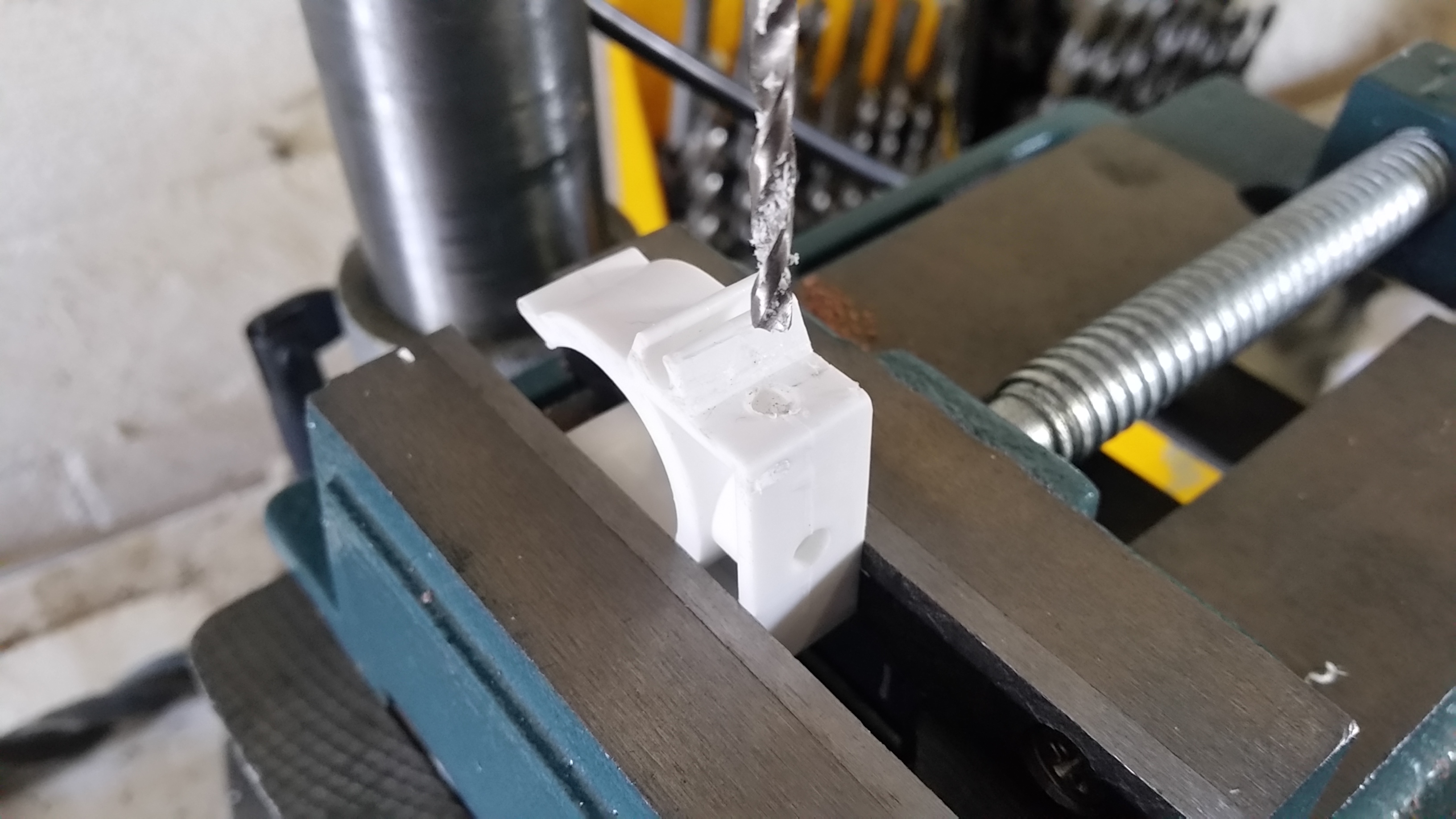
Start with a 2 mm pilot drill. Finish with a 3.5 mm drill bit.
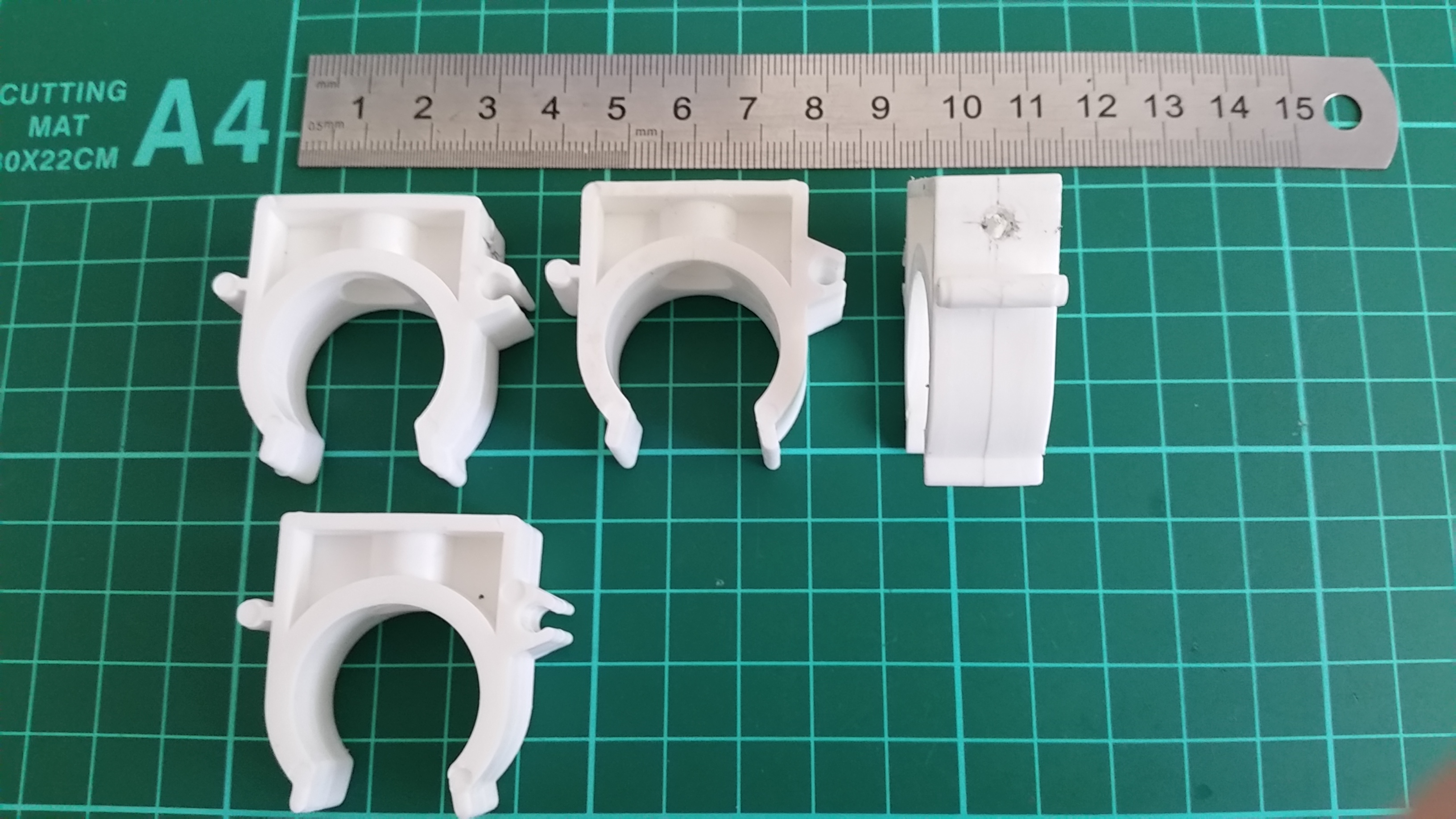
3.5 mm holes drilled through each clamp

3.1 mm element mount
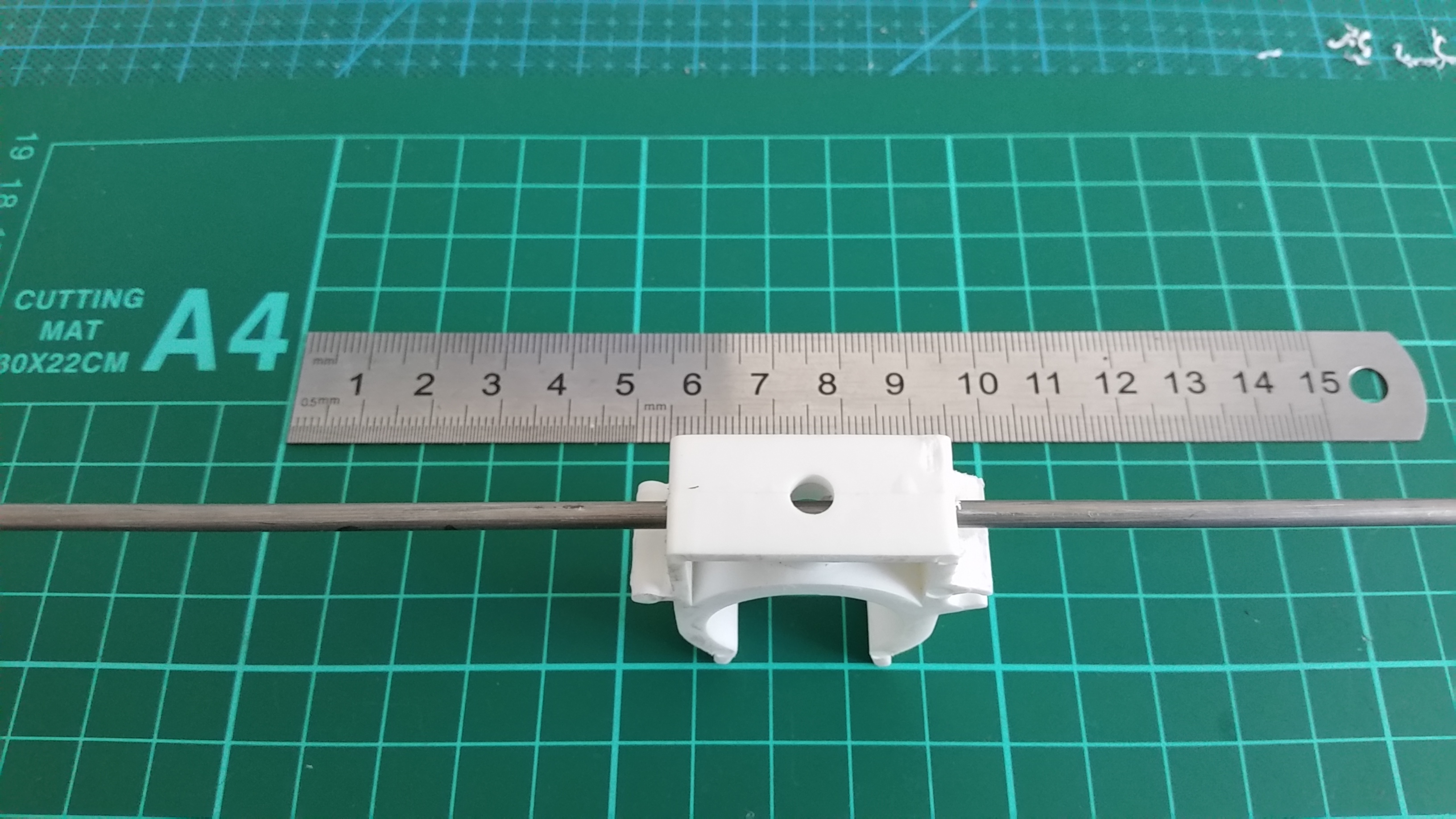
3.1 mm element mount
Mounting arrangement for the Reflector, D1 and D2 elements

27 mm PVC water pipe. Reflector, D1 and D2 mounting arrangement.
Driven Element mounting block preparation
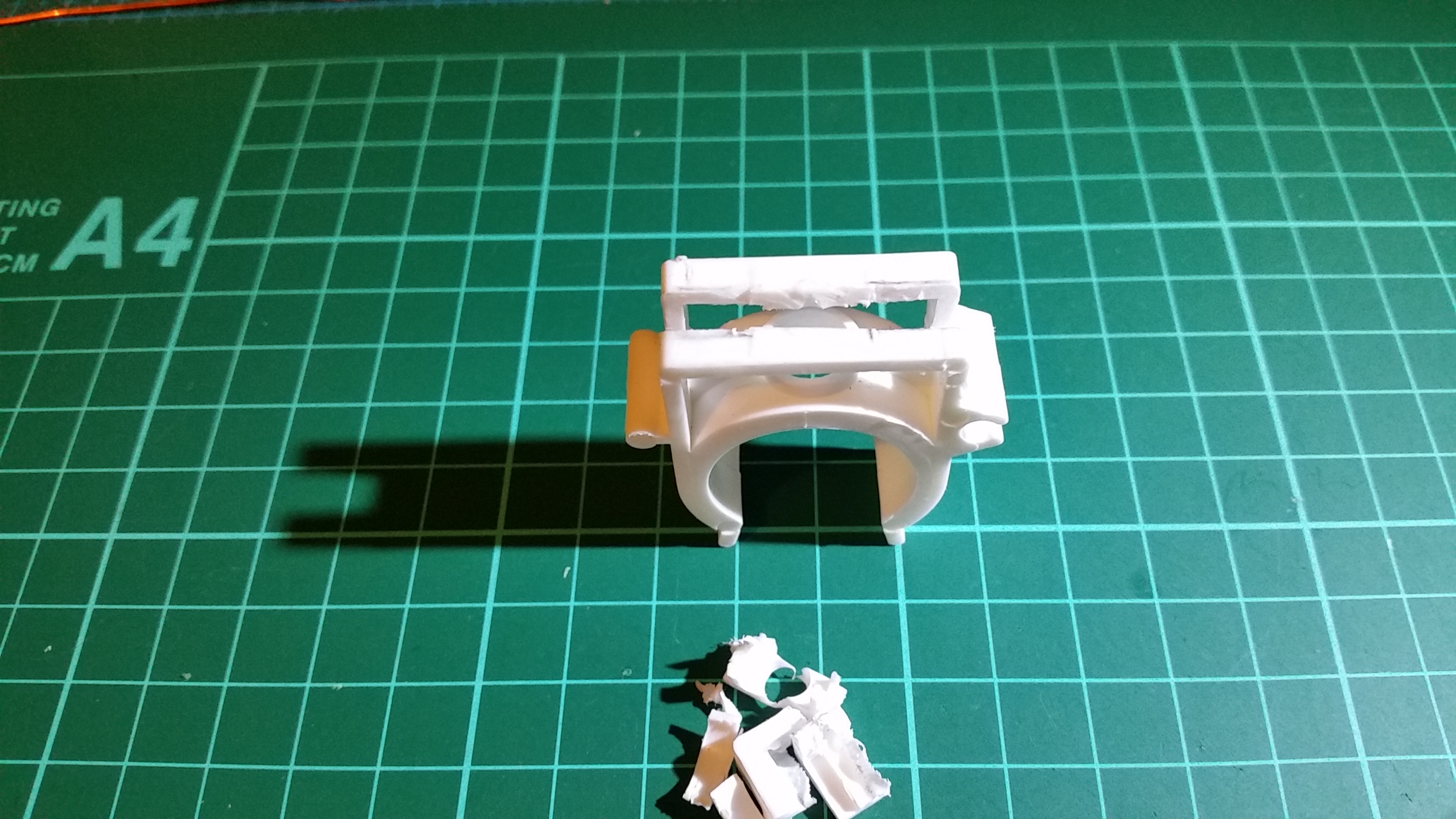
Prepare one pipe clamp for two brass terminal connectors

Brass terminal connectors resting in the slot

Solder one length of twisted braid to the outside of each terminal connector , before securing terminal connectors with cable ties

Brass terminal connectors secured with small cable ties and glued with two-part Araldite
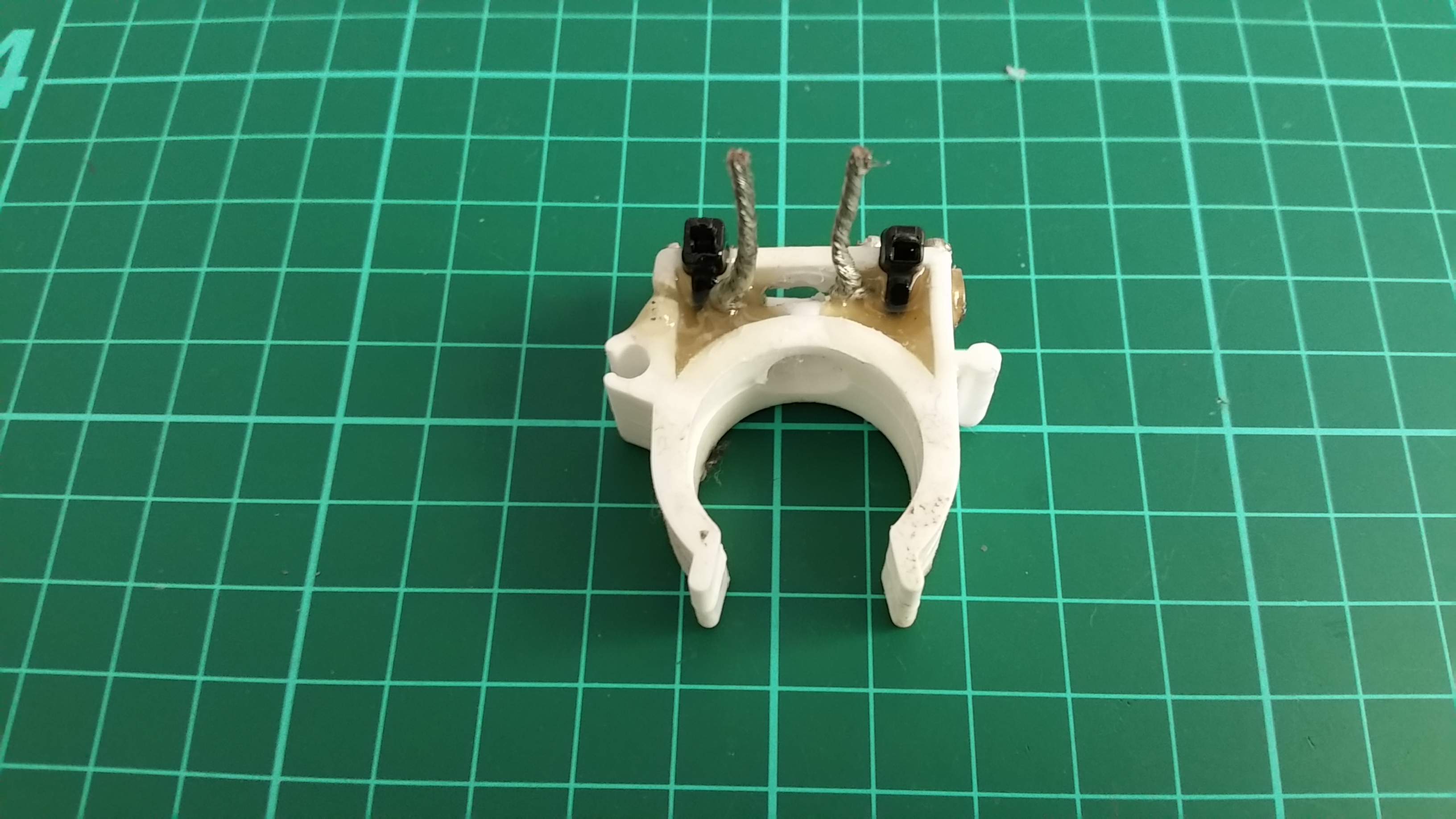
Driven element mounting block
Cut the Driven element (986 mm) in the center for two quater-wave elements each 493 mm long. Due to the extra wire soldered to each terminal connector, I had to trim 10 mm off each quarter-wave element to bring the resonant frequency up to 145 MHz.

Driven element center insulator

Coax choke soldered to the feed point. The combined choke/feedline is a single continuous length of RG58CU. The choke will take up 900 mm of feedline.
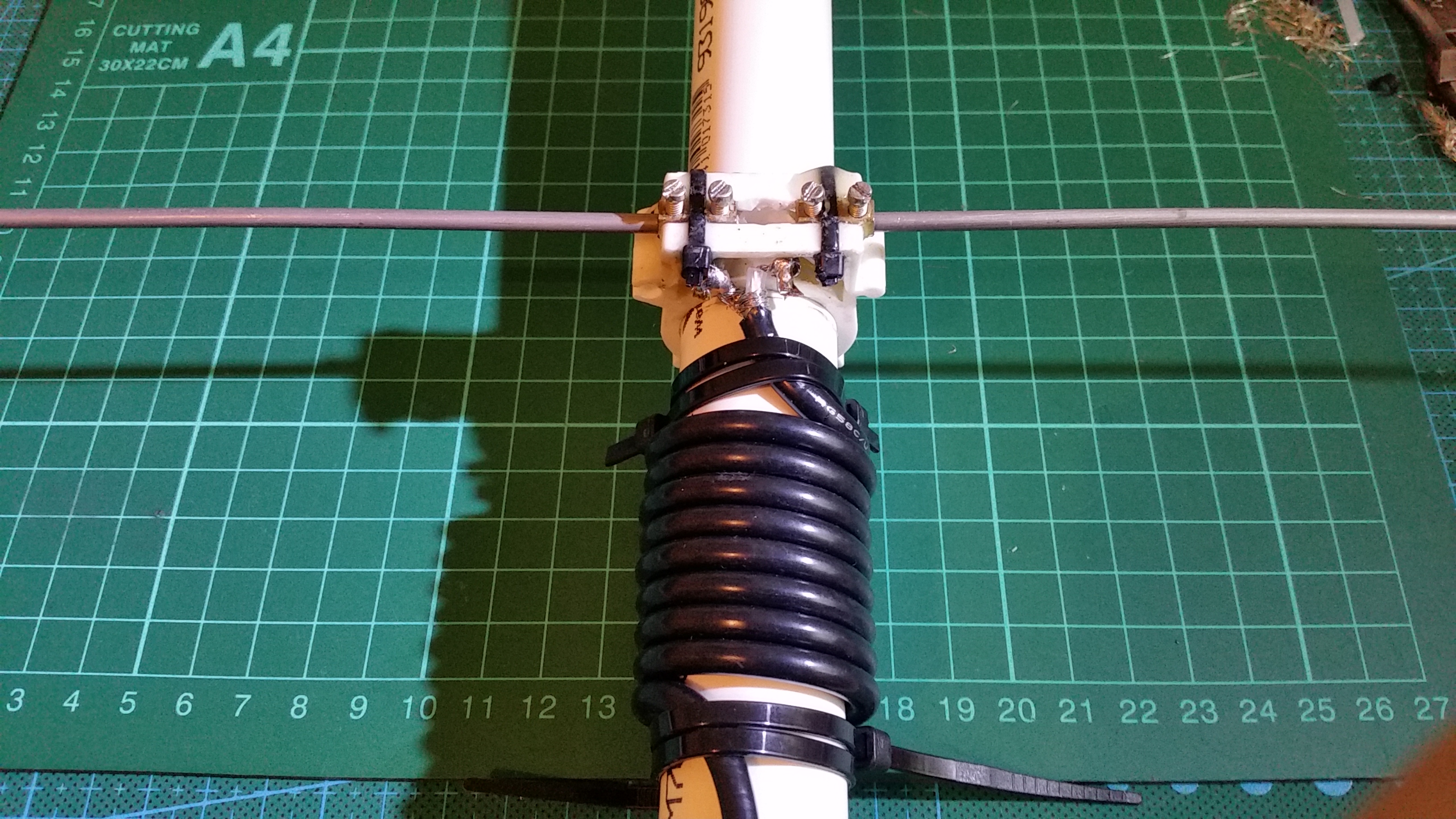
Common Mode Choke 9 turns – Series reactance at 145 MHz is approximately 3500 ohms.

25 mm pipe clamp bolted to a tripod quick release plate
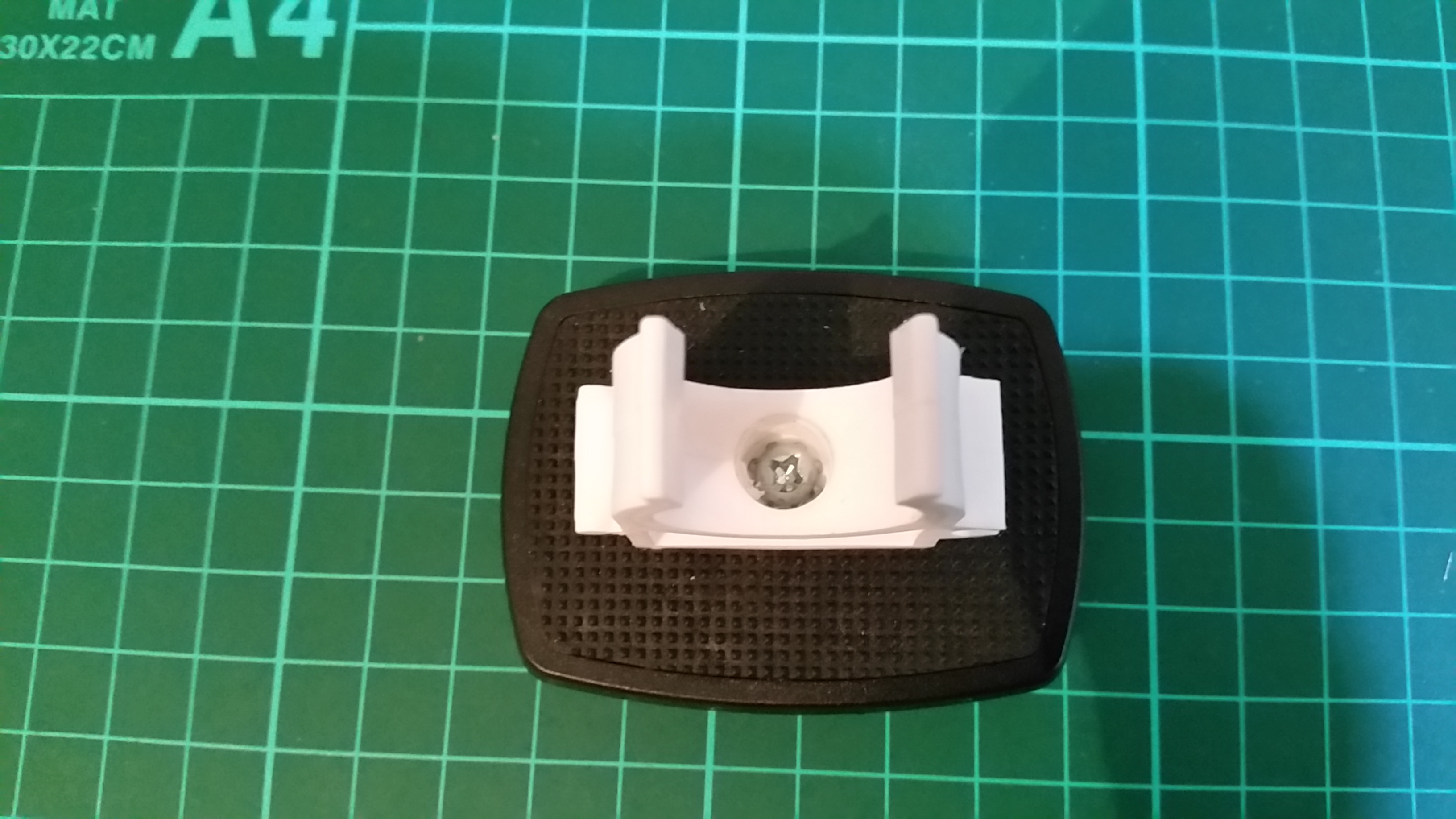
mount arrangment

Antenna mounted to a 1.4 metre camera tripod
This antenna can be held in your hand while operating a HT. For convenience I have shown the antenna mounted to a tripod. The combined weight with coax and tripod mount is 460 grams.
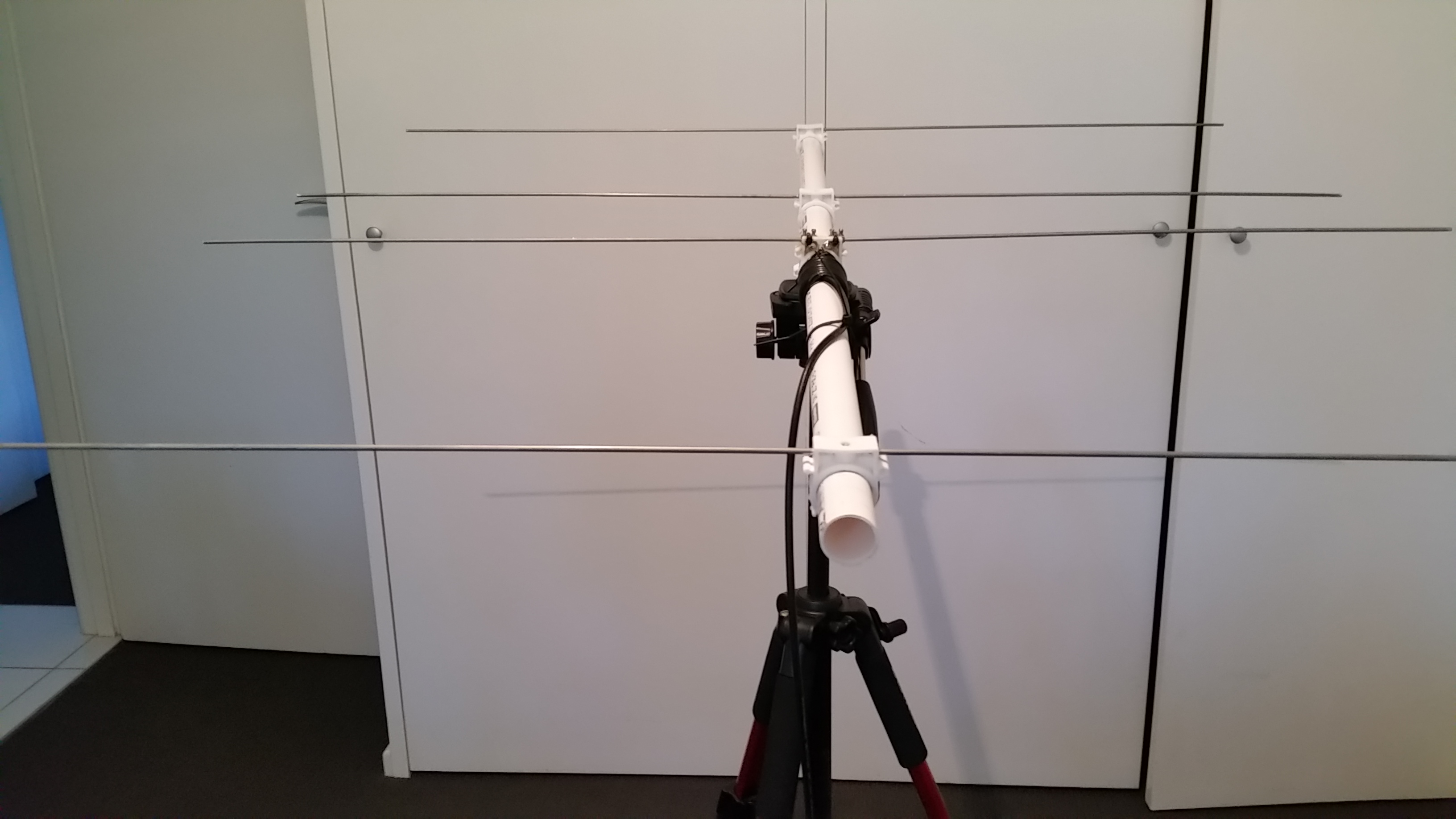
Finished – 4 element 2m 145 MHz DL6WU PVC Yagi for SOTA

Fine-tune element spacings for the lowest VSWR. Ensure you mark element positions on the PVC boom.
Once you have all elements in the correct position drill a hole through R, D1 and D2 clamps and into the boom, but don’t drill through the boom. You can insert a short length of dowel through each plastic clamp into the boom. This will ensure correct element position each time you assemble the antenna. 🙂

The Peak VK2/ST-068 in thick fog
Please feel free to copy the design 🙂
Post Update 29 November 2020
Old versus New. The new driven element insulator is fitted with 2 M3 20 mm brass stand off nuts. Each end of the driven elements is now threaded with M3 thread.
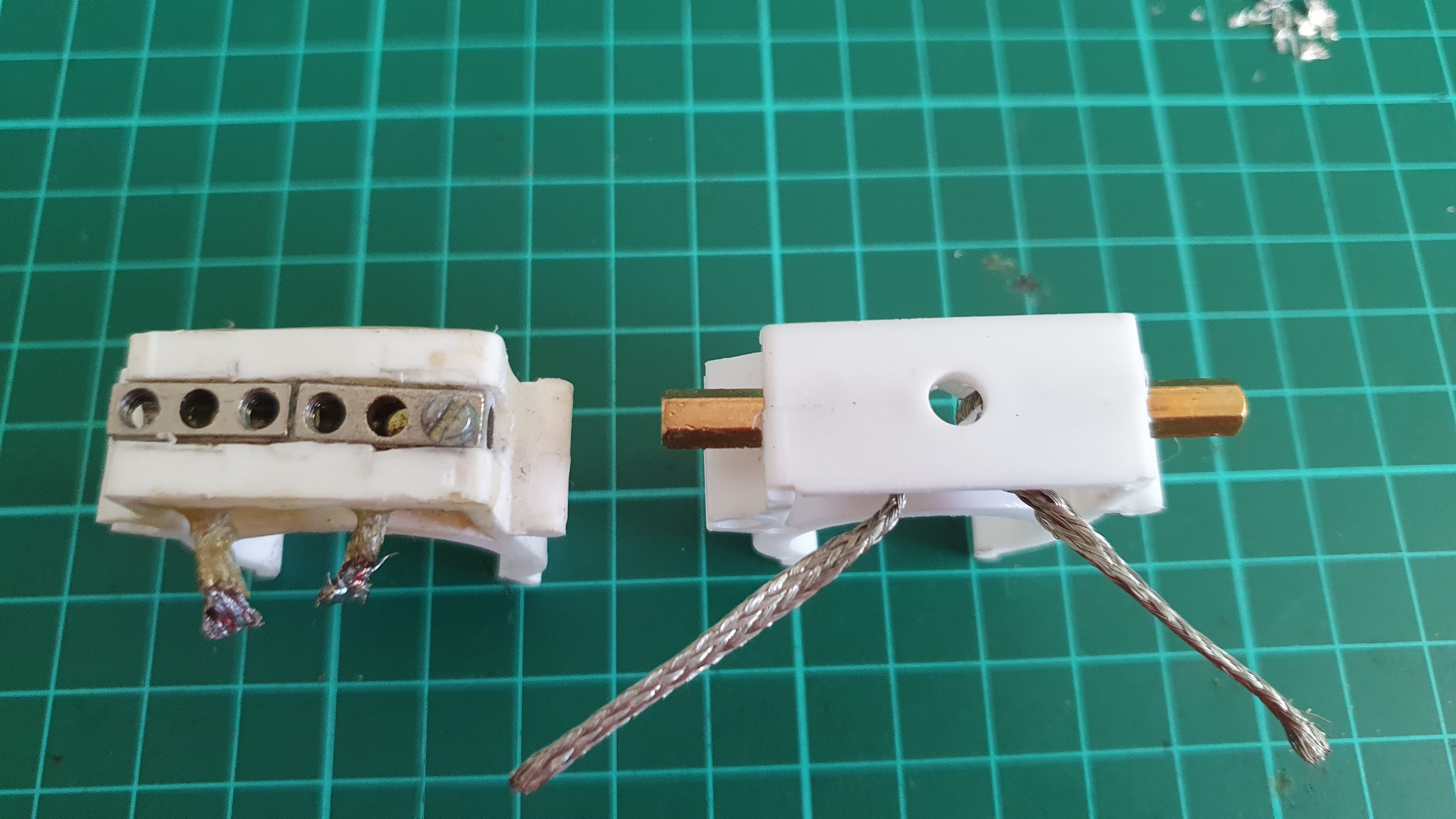
Old versus New driven element insulator

clamp fitted with two 3 mm x 20 mm long brass stand off nuts

driven elements tapped at one end with M3 thread

2m yagi driven element assembled
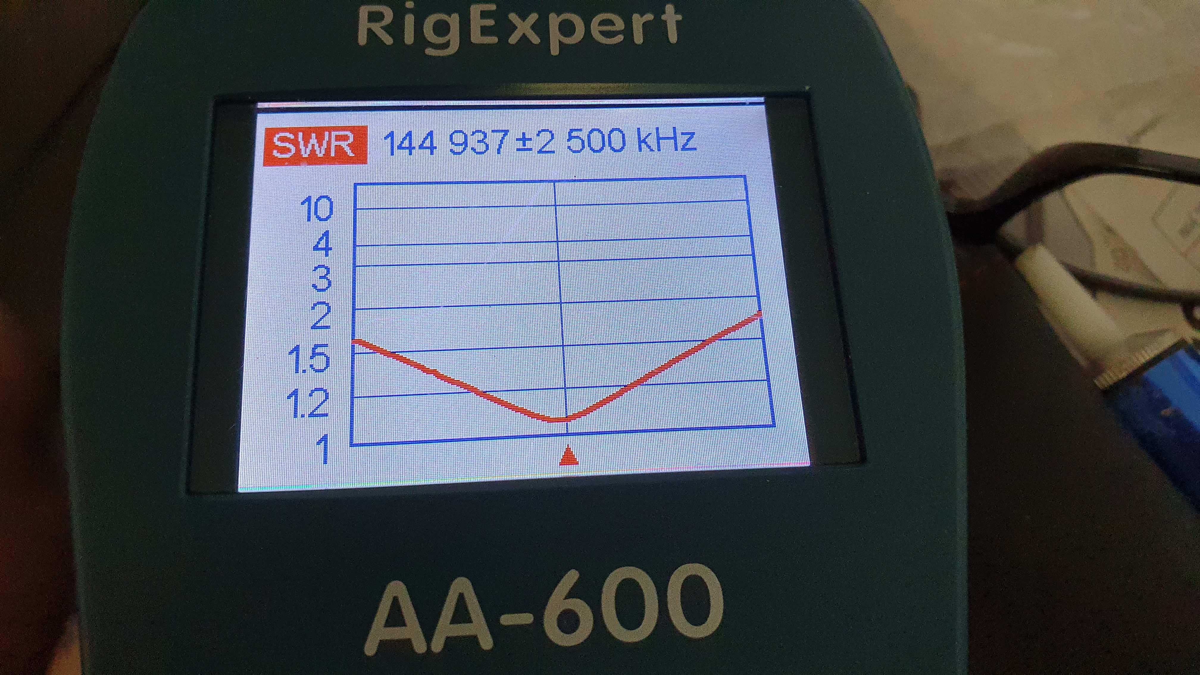
VSWR at 145 MHz
The 20 mm brass stand off nuts increase the length of the driven element by approximately 10 mm. Therefore you must shorten each 3.1 aluminium driven element by 10 mm and recheck the VSWR.
Next apply Araldite or an epoxy glue to the brass stand nuts on the inside of the plastic clamp. Avoid getting glue inside the 3 mm brass thread.
Last Update: 29 November 2020
73, Andrew VK1AD


